A
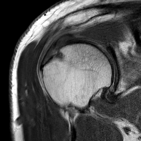
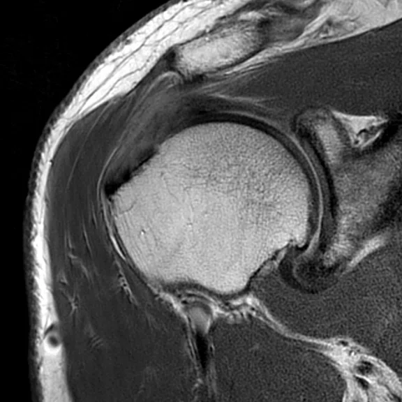
Figure 2.
Coronal PD FSE shoulder exam (A) without PROPELLER, 0.3 x 0.4 x 3 mm, 4:04 min., and (B) with PROPELLER, 0.3 x 0.3 x 3 mm, 3:43 min. Images courtesy of HSS
B
Figure 2.
Coronal PD FSE shoulder exam (A) without PROPELLER, 0.3 x 0.4 x 3 mm, 4:04 min., and (B) with PROPELLER, 0.3 x 0.3 x 3 mm, 3:43 min. Images courtesy of HSS
A
Figure 3.
(A) Hand image, axial PD FatSat, 0.3 x 0.3 x 3 mm, 8 cm FOV, 3:36 min.; (B) wrist image, coronal PD, 0.3 x 0.4 x 2 mm; and (C) finger image, sagittal PD FSE Flex, 0.3 x 0.4 x 2.5 mm, 2:17 min.
C
Figure 3.
(A) Hand image, axial PD FatSat, 0.3 x 0.3 x 3 mm, 8 cm FOV, 3:36 min.; (B) wrist image, coronal PD, 0.3 x 0.4 x 2 mm; and (C) finger image, sagittal PD FSE Flex, 0.3 x 0.4 x 2.5 mm, 2:17 min.
B
Figure 3.
(A) Hand image, axial PD FatSat, 0.3 x 0.3 x 3 mm, 8 cm FOV, 3:36 min.; (B) wrist image, coronal PD, 0.3 x 0.4 x 2 mm; and (C) finger image, sagittal PD FSE Flex, 0.3 x 0.4 x 2.5 mm, 2:17 min.
‡Not yet CE marked. Not available for sale in all regions.
A
Figure 1.
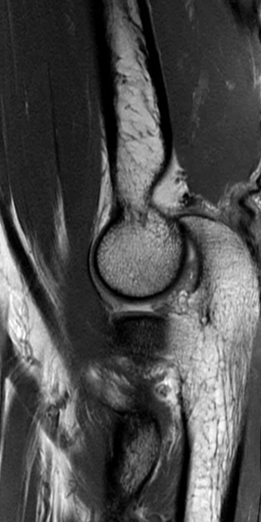
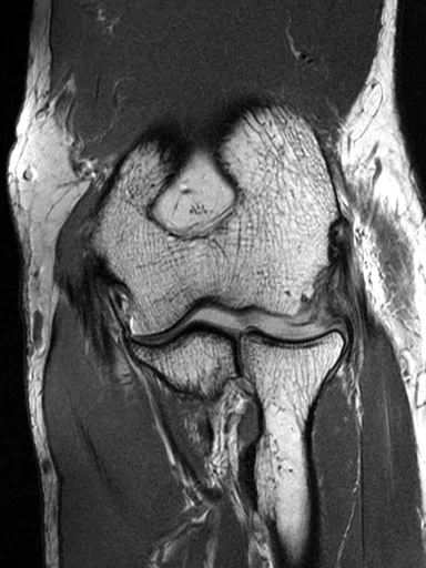
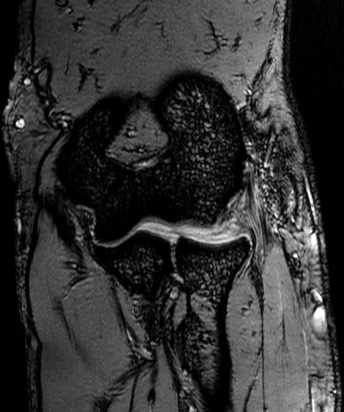
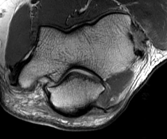
Elbow exam on patient weighing 260 lbs. and 5 ft. 7 in. tall with his arm by the side. (A) Sagittal PD FSE, 0.3 x 0.4 x 2.5 mm, 5:22 min.; (B) coronal PD FSE, 0.3 x 0.4 x 1.8 mm, 4:49 min.; (C) coronal T2* GRE, 0.3 x 0.6 x 1.7 mm, 5:23 min.; and (D) axial PD FSE, 0.3 x 0.5 x 3.5 mm, 3:01 min. Images courtesy of HSS
B
Figure 1.
Elbow exam on patient weighing 260 lbs. and 5 ft. 7 in. tall with his arm by the side. (A) Sagittal PD FSE, 0.3 x 0.4 x 2.5 mm, 5:22 min.; (B) coronal PD FSE, 0.3 x 0.4 x 1.8 mm, 4:49 min.; (C) coronal T2* GRE, 0.3 x 0.6 x 1.7 mm, 5:23 min.; and (D) axial PD FSE, 0.3 x 0.5 x 3.5 mm, 3:01 min. Images courtesy of HSS
C
Figure 1.
Elbow exam on patient weighing 260 lbs. and 5 ft. 7 in. tall with his arm by the side. (A) Sagittal PD FSE, 0.3 x 0.4 x 2.5 mm, 5:22 min.; (B) coronal PD FSE, 0.3 x 0.4 x 1.8 mm, 4:49 min.; (C) coronal T2* GRE, 0.3 x 0.6 x 1.7 mm, 5:23 min.; and (D) axial PD FSE, 0.3 x 0.5 x 3.5 mm, 3:01 min. Images courtesy of HSS
D
Figure 1.
Elbow exam on patient weighing 260 lbs. and 5 ft. 7 in. tall with his arm by the side. (A) Sagittal PD FSE, 0.3 x 0.4 x 2.5 mm, 5:22 min.; (B) coronal PD FSE, 0.3 x 0.4 x 1.8 mm, 4:49 min.; (C) coronal T2* GRE, 0.3 x 0.6 x 1.7 mm, 5:23 min.; and (D) axial PD FSE, 0.3 x 0.5 x 3.5 mm, 3:01 min. Images courtesy of HSS
Table 1.
Echo spacing (ESP) reductions with a standard 2D FSE acquisition on Discovery™ MR750 and SIGNA™ Premier, as a function of FOV and receive bandwidth (RBW). In several circumstances, the prescription could not be scanned on Discovery™ MR750, as noted. The protocol used for this comparison was a 2D FSE, 512 x 488 matrix, 2 mm slice thickness.
C
Figure 1.
Elbow exam on patient weighing 260 lbs. and 5 ft. 7 in. tall with his arm by the side. (A) Sagittal PD FSE, 0.3 x 0.4 x 2.5 mm, 5:22 min.; (B) coronal PD FSE, 0.3 x 0.4 x 1.8 mm, 4:49 min.; (C) coronal T2* GRE, 0.3 x 0.6 x 1.7 mm, 5:23 min.; and (D) axial PD FSE, 0.3 x 0.5 x 3.5 mm, 3:01 min. Images courtesy of HSS
D
Figure 1.
Elbow exam on patient weighing 260 lbs. and 5 ft. 7 in. tall with his arm by the side. (A) Sagittal PD FSE, 0.3 x 0.4 x 2.5 mm, 5:22 min.; (B) coronal PD FSE, 0.3 x 0.4 x 1.8 mm, 4:49 min.; (C) coronal T2* GRE, 0.3 x 0.6 x 1.7 mm, 5:23 min.; and (D) axial PD FSE, 0.3 x 0.5 x 3.5 mm, 3:01 min. Images courtesy of HSS
A
Figure 1.
Elbow exam on patient weighing 260 lbs. and 5 ft. 7 in. tall with his arm by the side. (A) Sagittal PD FSE, 0.3 x 0.4 x 2.5 mm, 5:22 min.; (B) coronal PD FSE, 0.3 x 0.4 x 1.8 mm, 4:49 min.; (C) coronal T2* GRE, 0.3 x 0.6 x 1.7 mm, 5:23 min.; and (D) axial PD FSE, 0.3 x 0.5 x 3.5 mm, 3:01 min. Images courtesy of HSS
B
Figure 1.
Elbow exam on patient weighing 260 lbs. and 5 ft. 7 in. tall with his arm by the side. (A) Sagittal PD FSE, 0.3 x 0.4 x 2.5 mm, 5:22 min.; (B) coronal PD FSE, 0.3 x 0.4 x 1.8 mm, 4:49 min.; (C) coronal T2* GRE, 0.3 x 0.6 x 1.7 mm, 5:23 min.; and (D) axial PD FSE, 0.3 x 0.5 x 3.5 mm, 3:01 min. Images courtesy of HSS
result
PREVIOUS
${prev-page}
NEXT
${next-page}
Subscribe Now
Manage Subscription
FOLLOW US
contact us • privacy policy • terms & conditions
© 2023 GE HealthCare. GE is a trademark of the General Electric Company used under trademark license.


SPOTLIGHT
A coil for all joints in MSK imaging
A coil for all joints in MSK imaging
Patients come in all shapes and sizes. However, traditional hard shell MR coils do not fit all patients, all the time, and this can lead to poor signal and poor image quality. The lack of dedicated coils for orthopedic imaging presents challenges in patient positioning and often leads to longer scan times and lower signal-to-noise ratio. Coupled with the high performance gradient of the wide bore SIGNA™ Premier system, AIR™ Multi-Purpose (MP) Coils‡ provide flexibility and comfort in positioning, larger Z-coverage of the body and consistent and excellent image quality. Together, they aid in patient diagnosis and surgical planning at the Hospital for Special Surgery in New York.
Patients come in all shapes and sizes. However, traditional hard shell MR coils do not fit all patients, all the time, and this can lead to poor signal and poor image quality. The lack of dedicated coils for orthopedic imaging presents challenges in patient positioning and often leads to longer scan times and lower signal-to-noise ratio. Coupled with the high performance gradient of the wide bore SIGNA™ Premier system, AIR™ Multi-Purpose (MP) Coils‡ provide flexibility and comfort in positioning, larger Z-coverage of the body and consistent and excellent image quality. Together, they aid in patient diagnosis and surgical planning at the Hospital for Special Surgery in New York.
AIR™ MP Coils were designed to address the need for total positioning freedom with 360-degree coverage in patients of all shapes and sizes. With an adaptive design and both 20- and 21 channel coils that are 38 percent lighter per channel compared to conventional technology, AIR™ MP Coils deliver the coverage needed for a variety of orthopedic, body and cardiac exams.
Figure 1.
Elbow exam on patient weighing 260 lbs. and 5 ft. 7 in. tall with his arm by the side. (A) Sagittal PD FSE, 0.3 x 0.4 x 2.5 mm, 5:22 min.; (B) coronal PD FSE, 0.3 x 0.4 x 1.8 mm, 4:49 min.; (C) coronal T2* GRE, 0.3 x 0.6 x 1.7 mm, 5:23 min.; and (D) axial PD FSE, 0.3 x 0.5 x 3.5 mm, 3:01 min.
Figure 1.
Elbow exam on patient weighing 260 lbs. and 5 ft. 7 in. tall with his arm by the side. (A) Sagittal PD FSE, 0.3 x 0.4 x 2.5 mm, 5:22 min.; (B) coronal PD FSE, 0.3 x 0.4 x 1.8 mm, 4:49 min.; (C) coronal T2* GRE, 0.3 x 0.6 x 1.7 mm, 5:23 min.; and (D) axial PD FSE, 0.3 x 0.5 x 3.5 mm, 3:01 min. Images courtesy of HSS
“The challenge in orthopedic imaging is the lack of dedicated coils,” says Hollis Potter, MD, Chairman, Department of Radiology and Imaging at the Hospital for Special Surgery (HSS). As a result, coils designed for other body parts are often used in orthopedic MR imaging.
Take for example the elbow. There is a tremendous degree of rotation in the forearm; however, above the elbow joint, the arm has less rotation. Positioning is very important to obtain high-quality images without the need for a “superman” position where the patient’s arms are extended straight up above their head, creating traction on the shoulder and brachial plexus.
With traditional coils, Dr. Potter would regularly see evidence of B1 inhomogeneities, degradation in the images and a lack of homogeneous fat suppression on elbow images. These were often the result of air gaps between the skin and coils and the inability to completely “wrap” the elbow or overlapping of coil elements due to poor fit.
Positioning the orthopedic patient with a traditional coil is not only more difficult due to its rigid structure, but often requires additional time for localization during scanning. According to Dr. Potter, it would not be unusual to see four different localizer MR scans as the technologist tried to obtain the ideal position for optimal image quality, and often positioning a patient in a hard-shell-cased coil is a difficult task. This is not the case with the AIR™ MP Coils.
“The AIR™ Coils have been great for us,” Dr. Potter says. “They are like fabric, so it doesn’t matter how big our patient’s elbow or arm is. We can wrap the coil around the elbow and overlap elements without perceivable interference or any negative impact on image quality.”
In addition to added patient comfort, the technologist can place the AIR™ MP Coil in areas that were previously difficult to access, such as around the neck for a brachial plexus study. “Traditional flex coils are not completely flexible, can be uncomfortable and may impact image quality,” says Darryl Sneag, MD, radiologist at HSS.
The AIR™ MP Coils provide larger Z-coverage of the body area and are particularly useful when imaging an extremity.
“To image a large tumor or to evaluate nerves from the shoulder to the wrist, our technologist had to reposition the coil three to four times to cover the entire anatomy,” explains Dr. Sneag. “Now, we only have two position changes. From my perspective, the biggest advantage is the increase in Z-coverage while still achieving the equivalent in-plane spatial resolution.”
Although GE Healthcare’s Discovery™ MR750w with GEM had an integrated posterior array providing added flexibility in coil positioning, the SIGNA™ Premier with the integrated AIR™ Posterior Array (PA), AIR™ Anterior Array (AA) and the newly launched AIR™ MP Coils, which come in two different channel counts, deliver added flexibility and coil combinations. With the AIR™ Coils, patients are more comfortable and this leads to a better patient experience.
Patient comfort also impacts image quality and study reproducibility by helping to reduce patient movement. According to Dr. Potter, having high-quality images that are reproducible across MR exams can reduce radiologist fatigue when reading.
“When we have consistent, superior image quality, it is hard not to get excited,” says Dr. Potter.
“The superior gradient performance of the SIGNA™ Premier system with solid gradient linearity off of isocenter, combined with the flexibility of the AIR™ Coils, provides us with some of the best and most consistent images that I have encountered across platforms.”
Dr. Hollis Potter
For Dr. Sneag, the ability to precisely visualize lesions and nerves, and identify structural changes in peripheral nerves to give patients a reason why they are in pain or weak, is the most significant impact of the combined improvements from AIR™ MP Coils, new pulse sequences and higher performance gradients on SIGNA™ Premier.
“These improvements are not to be taken lightly — these technologies are making a strong impact,” adds Dr. Potter. “It is not just the ability to provide the information we need to confidently diagnose conditions that were previously considered a diagnosis of exclusion, but we now find focal lesions that are amenable to surgery. These images provide an essential roadmap to refine the surgical exposure.”
The impact is not just in diagnosis, but also in surgical planning. Drs. Sneag and Potter can deliver a more targeted approach to answer the clinical question, such as pinpointing precisely where the abnormality is located. This approach can help reduce serial imaging, as well as the length of time for the surgical procedure.
In several instances, Dr. Sneag has marked areas on patient scans that have taken a lot of the guesswork out of the procedure for surgeons. In many cases, the surgeon has been able to reduce the incision size significantly because they knew exactly where to operate.
From a research perspective, the results have been equally impressive with AIR™ Coils and SIGNA™ Premier.
“With SIGNA™ Premier, we now have the ability to actively use 120 elements,” says Dr. Sneag. “That allows us to think outside the box — previously we only had 32 channels. As we are looking at higher channel coils or combining coils, there are so many more options.”
SIGNA™ Premier has gradient performance advantages over the Discovery™ MR750, as evidenced by shorter echo spacing, which leads to sharper images (Table 1). In addition, SIGNA™ Premier has the capacity for more elements, as well as more receivers. By adding the high-density AIR™ Coils, HSS can now scan with the densest coil packing per volume, enabling the use of the highest independent channels for each imaging volume. And that is a benefit for clinicians and patients alike.
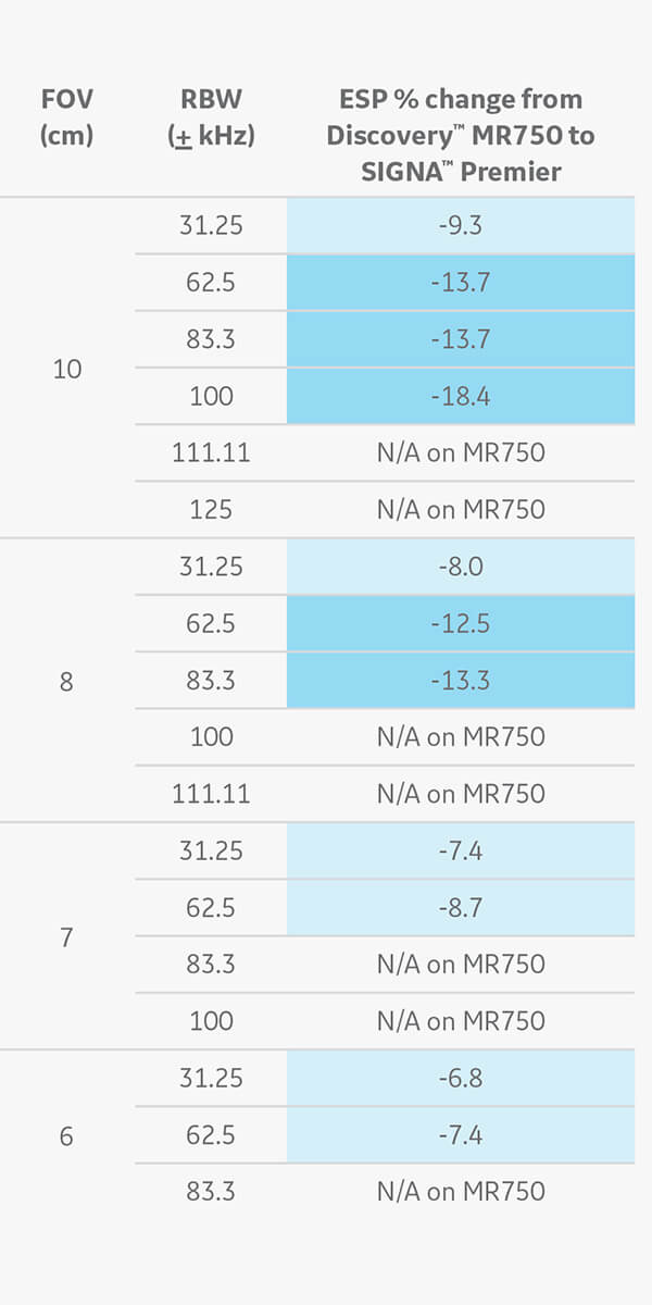
Table 1.
Echo spacing (ESP) reductions with a standard 2D FSE acquisition on Discovery™ MR750 and SIGNA™ Premier, as a function of FOV and receive bandwidth (RBW). In several circumstances, the prescription could not be scanned on Discovery™ MR750, as noted. The protocol used for this comparison was a 2D FSE, 512 x 488 matrix, 2 mm slice thickness.


