D
Figure #.
Figure Copy.
‡Not licensed in accordance with Canadian law. Not available for sale in Canada. Not CE marked. Not available for sale in all regions.
‡Not licensed in accordance with Canadian law. Not available for sale in Canada. Not CE marked. Not available for sale in all regions.
‡Not licensed in accordance with Canadian law. Not available for sale in Canada. Not CE marked. Not available for sale in all regions.
A
Figure 1.
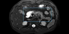
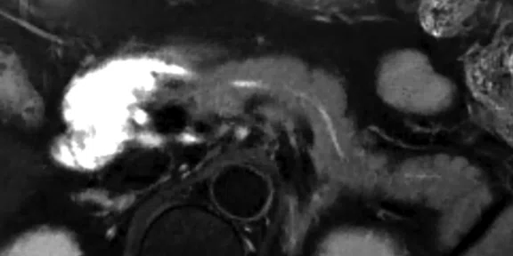
AIR Technology™ enables the use of higher parallel imaging factors with improved SNR for high-resolution imaging and reduced scan times. (A) Axial T2w FatSat acquisition with PROPELLER MB, 0.6 x 0.6 x 4 mm, ARC factor of 4, 4:24 min.; (B) ROI in (A) magnified.
B
Figure 1.
AIR Technology™ enables the use of higher parallel imaging factors with improved SNR for high-resolution imaging and reduced scan times. (A) Axial T2w FatSat acquisition with PROPELLER MB, 0.6 x 0.6 x 4 mm, ARC factor of 4, 4:24 min.; (B) ROI in (A) magnified.
A
Figure 2.
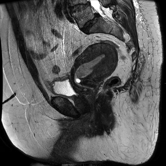
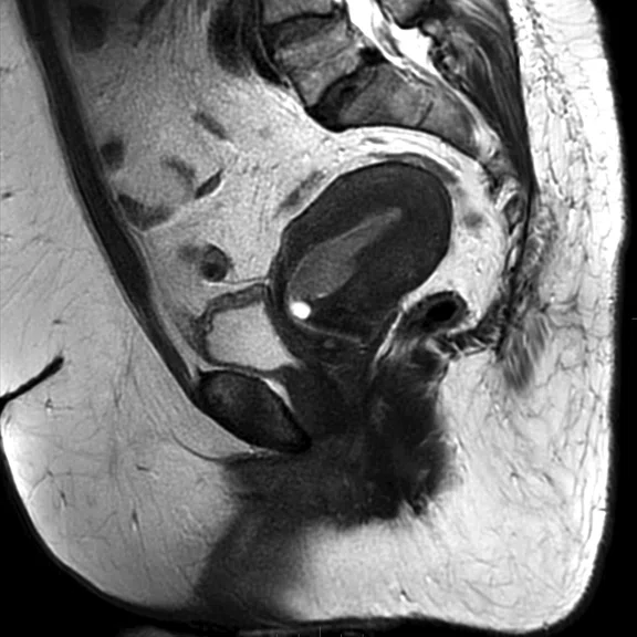
A female weighing 287 lbs. (130 kg) referred for MR imaging of the pelvis. (A) Sagittal T2w frFSE, 0.8 x 0.9 x 4 mm, 6:08 min.; (B) Sagittal T2w PROPELLER MB, 0.9 x 0.9 x 4 mm, 3:02 min.
B
Figure 2.
A female weighing 287 lbs. (130 kg) referred for MR imaging of the pelvis. (A) Sagittal T2w frFSE, 0.8 x 0.9 x 4 mm, 6:08 min.; (B) Sagittal T2w PROPELLER MB, 0.9 x 0.9 x 4 mm, 3:02 min.
A
Figure 3.
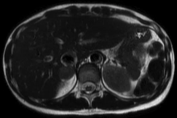
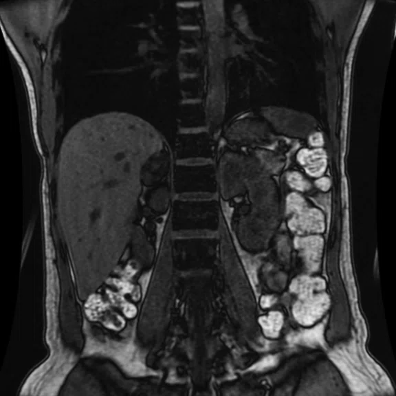
Patient with an adrenal mass. (A) Axial T2w SSFSE, 1.1 x 1.8 x 5 mm, 18 sec.; (B) Axial DW-EPI, 2.8 x 2.8 x 5 mm, 3:49 min. (RTr); (C-E) Coronal LAVA Flex, 1.4 x 1.6 x 3 mm, 16 sec.; (C) water, (D) in-phase and (E) out-of-phase.
B
Figure 3.
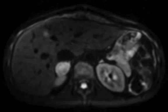
Patient with an adrenal mass. (A) Axial T2w SSFSE, 1.1 x 1.8 x 5 mm, 18 sec.; (B) Axial DW-EPI, 2.8 x 2.8 x 5 mm, 3:49 min. (RTr); (C-E) Coronal LAVA Flex, 1.4 x 1.6 x 3 mm, 16 sec.; (C) water, (D) in-phase and (E) out-of-phase.
C
Figure 3.
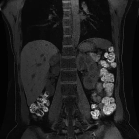
Patient with an adrenal mass. (A) Axial T2w SSFSE, 1.1 x 1.8 x 5 mm, 18 sec.; (B) Axial DW-EPI, 2.8 x 2.8 x 5 mm, 3:49 min. (RTr); (C-E) Coronal LAVA Flex, 1.4 x 1.6 x 3 mm, 16 sec.; (C) water, (D) in-phase and (E) out-of-phase.
D
Figure 3.
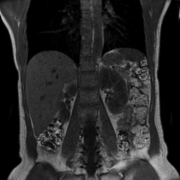
Patient with an adrenal mass. (A) Axial T2w SSFSE, 1.1 x 1.8 x 5 mm, 18 sec.; (B) Axial DW-EPI, 2.8 x 2.8 x 5 mm, 3:49 min. (RTr); (C-E) Coronal LAVA Flex, 1.4 x 1.6 x 3 mm, 16 sec.; (C) water, (D) in-phase and (E) out-of-phase.
E
Figure 3.
Patient with an adrenal mass. (A) Axial T2w SSFSE, 1.1 x 1.8 x 5 mm, 18 sec.; (B) Axial DW-EPI, 2.8 x 2.8 x 5 mm, 3:49 min. (RTr); (C-E) Coronal LAVA Flex, 1.4 x 1.6 x 3 mm, 16 sec.; (C) water, (D) in-phase and (E) out-of-phase.
A
Figure 4.
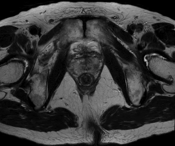
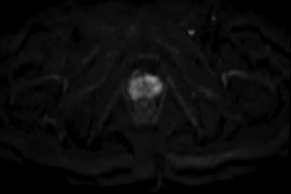
Prostate cancer patient (A) Axial T2w PROPELLER MB, 0.6 x 0.7 x 4 mm, 3:25 min; (B) EPI DWI b1000, 2.3 x 2.3 x 4 mm, 2:08 min.; and (C) FOCUS DWI, b1000, 1.5 x 1.5 x 4 mm, 4:10 min.
B
Figure 4.
Prostate cancer patient (A) Axial T2w PROPELLER MB, 0.6 x 0.7 x 4 mm, 3:25 min; (B) EPI DWI b1000, 2.3 x 2.3 x 4 mm, 2:08 min.; and (C) FOCUS DWI, b1000, 1.5 x 1.5 x 4 mm, 4:10 min.
C
Figure 4.
Prostate cancer patient (A) Axial T2w PROPELLER MB, 0.6 x 0.7 x 4 mm, 3:25 min; (B) EPI DWI b1000, 2.3 x 2.3 x 4 mm, 2:08 min.; and (C) FOCUS DWI, b1000, 1.5 x 1.5 x 4 mm, 4:10 min.
A
Figure 5.
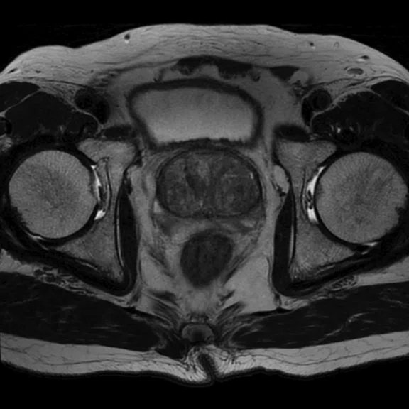
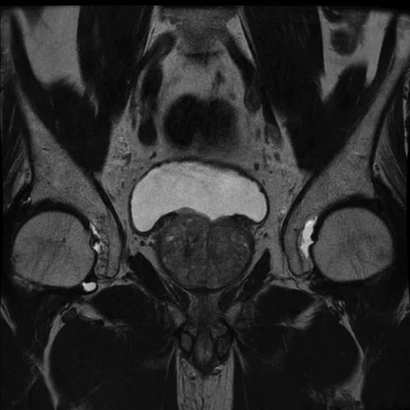
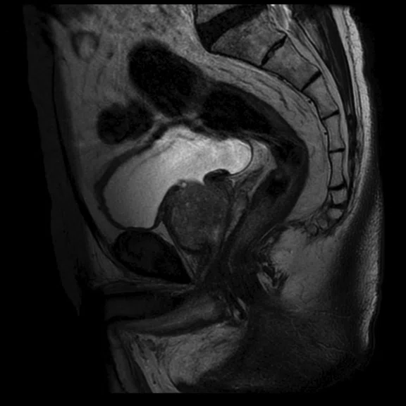
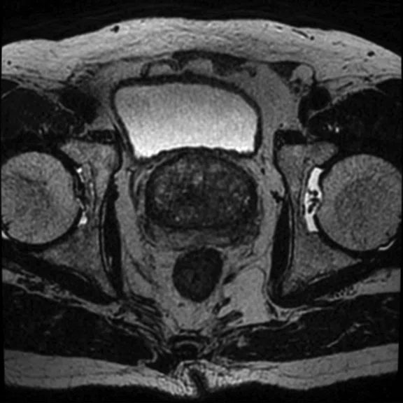
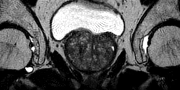
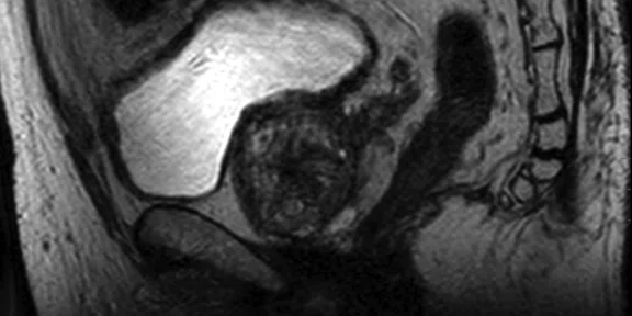
Prostate exam using HyperCube. (A-C) Conventional 2D T2w in 3 planes. (D-F) T2w with HyperCube enables (E-F) thin-slice imaging. (A) Axial T2w, 0.6 x 0.8 x 4 mm, 3:42 min.; (B) Coronal T2w, 0.6 x 0.8 x 4 mm, 3:25 min.; (C) Sagittal T2w, 0.6 x 0.8 x 4 mm, 2:36 min.; and (D-F) T2w with HyperCube acquired in the Axial plane and reformatted to (E) Coronal and (F) Sagittal, 0.9 x 0.9 x 2 mm, 3:54 min.
B
Figure 5.
Prostate exam using HyperCube. (A-C) Conventional 2D T2w in 3 planes. (D-F) T2w with HyperCube enables (E-F) thin-slice imaging. (A) Axial T2w, 0.6 x 0.8 x 4 mm, 3:42 min.; (B) Coronal T2w, 0.6 x 0.8 x 4 mm, 3:25 min.; (C) Sagittal T2w, 0.6 x 0.8 x 4 mm, 2:36 min.; and (D-F) T2w with HyperCube acquired in the Axial plane and reformatted to (E) Coronal and (F) Sagittal, 0.9 x 0.9 x 2 mm, 3:54 min.
C
Figure 5.
Prostate exam using HyperCube. (A-C) Conventional 2D T2w in 3 planes. (D-F) T2w with HyperCube enables (E-F) thin-slice imaging. (A) Axial T2w, 0.6 x 0.8 x 4 mm, 3:42 min.; (B) Coronal T2w, 0.6 x 0.8 x 4 mm, 3:25 min.; (C) Sagittal T2w, 0.6 x 0.8 x 4 mm, 2:36 min.; and (D-F) T2w with HyperCube acquired in the Axial plane and reformatted to (E) Coronal and (F) Sagittal, 0.9 x 0.9 x 2 mm, 3:54 min.
D
Figure 5.
Prostate exam using HyperCube. (A-C) Conventional 2D T2w in 3 planes. (D-F) T2w with HyperCube enables (E-F) thin-slice imaging. (A) Axial T2w, 0.6 x 0.8 x 4 mm, 3:42 min.; (B) Coronal T2w, 0.6 x 0.8 x 4 mm, 3:25 min.; (C) Sagittal T2w, 0.6 x 0.8 x 4 mm, 2:36 min.; and (D-F) T2w with HyperCube acquired in the Axial plane and reformatted to (E) Coronal and (F) Sagittal, 0.9 x 0.9 x 2 mm, 3:54 min.
E
Figure 5.
Prostate exam using HyperCube. (A-C) Conventional 2D T2w in 3 planes. (D-F) T2w with HyperCube enables (E-F) thin-slice imaging. (A) Axial T2w, 0.6 x 0.8 x 4 mm, 3:42 min.; (B) Coronal T2w, 0.6 x 0.8 x 4 mm, 3:25 min.; (C) Sagittal T2w, 0.6 x 0.8 x 4 mm, 2:36 min.; and (D-F) T2w with HyperCube acquired in the Axial plane and reformatted to (E) Coronal and (F) Sagittal, 0.9 x 0.9 x 2 mm, 3:54 min.
F
Figure 5.
Prostate exam using HyperCube. (A-C) Conventional 2D T2w in 3 planes. (D-F) T2w with HyperCube enables (E-F) thin-slice imaging. (A) Axial T2w, 0.6 x 0.8 x 4 mm, 3:42 min.; (B) Coronal T2w, 0.6 x 0.8 x 4 mm, 3:25 min.; (C) Sagittal T2w, 0.6 x 0.8 x 4 mm, 2:36 min.; and (D-F) T2w with HyperCube acquired in the Axial plane and reformatted to (E) Coronal and (F) Sagittal, 0.9 x 0.9 x 2 mm, 3:54 min.
A
Figure 6.
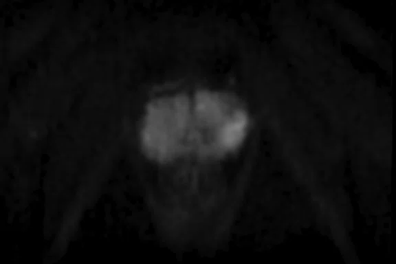
Patient referred for prostate exam. (A) DWI b1000, 2.3 x 2.3 x 4 mm, 2:08 min.; (B) FOCUS b1000, 1.5 x 1.8 x 4 mm, 4:10 min.; and (C) MUSE 3 shot b1000, 1.6 x 1.6 x 4 mm, 4:15 min.
C
Figure 6.
Patient referred for prostate exam. (A) DWI b1000, 2.3 x 2.3 x 4 mm, 2:08 min.; (B) FOCUS b1000, 1.5 x 1.8 x 4 mm, 4:10 min.; and (C) MUSE 3 shot b1000, 1.6 x 1.6 x 4 mm, 4:15 min.
B
Figure 6.
Patient referred for prostate exam. (A) DWI b1000, 2.3 x 2.3 x 4 mm, 2:08 min.; (B) FOCUS b1000, 1.5 x 1.8 x 4 mm, 4:10 min.; and (C) MUSE 3 shot b1000, 1.6 x 1.6 x 4 mm, 4:15 min.
A
Figure 7.
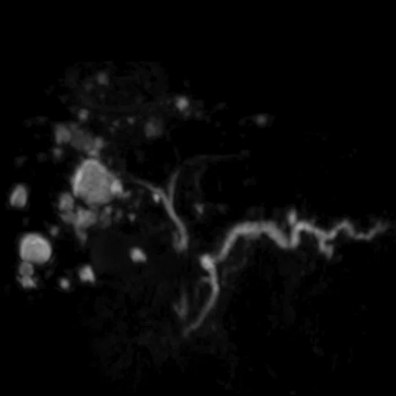
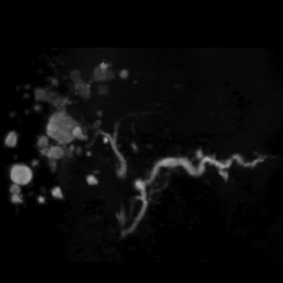
Comparison of MRCP exam with and without HyperSense. Scan time was reduced 30% with HyperSense. (A) Conventional MRCP RTr, 0.7 x 1.1 x 1.6 mm, 3:51 sec. and (B) MRCP RTr with HyperSense, 0.7 x 0.9 x 1.6 mm, 2:45 min.
B
Figure 7.
Comparison of MRCP exam with and without HyperSense. Scan time was reduced 30% with HyperSense. (A) Conventional MRCP RTr, 0.7 x 1.1 x 1.6 mm, 3:51 sec. and (B) MRCP RTr with HyperSense, 0.7 x 0.9 x 1.6 mm, 2:45 min.
result


PREVIOUS
${prev-page}
NEXT
${next-page}
Subscribe Now
Manage Subscription
FOLLOW US
Contact Us • Cookie Preferences • Privacy Policy • California Privacy PolicyDo Not Sell or Share My Personal Information • Terms & Conditions • Security
© 2024 GE HealthCare. GE is a trademark of General Electric Company. Used under trademark license.
IN PRACTICE
An upgrade that meets the expectation for higher resolution, SNR and productivity
An upgrade that meets the expectation for higher resolution, SNR and productivity
After upgrading its SIGNA™ Architect to the latest SIGNA™Works productivity platform and acquiring the AIR Technology™‡ Anterior Array (AA), Osaka University Hospital is delivering exceptional MR imaging that also promotes patient-centered care—two tenets of the hospital’s core philosophy. The combination of these three advanced technologies is delivering excellent image uniformity across a wide range of patients and clinical exams.
After upgrading its SIGNA™ Architect to the latest SIGNA™Works productivity platform and acquiring the AIR Technology™‡ Anterior Array (AA), Osaka University Hospital is delivering exceptional MR imaging that also promotes patient-centered care—two tenets of the hospital’s core philosophy. The combination of these three advanced technologies is delivering excellent image uniformity across a wide range of patients and clinical exams.
For nearly 150 years, Osaka University Hospital (originally Osaka Medical School, circa 1869) has served the residents of Osaka and fostered the education of medical professionals throughout the region. The hospital’s dedication to providing high-quality medical care is centered on the belief that adopting new and advanced technologies further promotes patient-centered, safe and reliable holistic care that contributes to the society.
"At Osaka University Hospital, we always seek the latest innovative technology to provide the best clinical performance and patient care," says Masatoshi Hori, MD, PhD, Associate Professor, Department of Radiology at Osaka University Hospital. With this philosophy, the department recently upgraded its existing Discovery™ MR750w 3.0T to SIGNA™ Architect and also acquired the AIR Technology™ AA.
"Our key expectation for MR is higher resolution, higher signal-to-noise ratio and higher temporal resolution," Professor Hori says. "This upgrade completely meets our expectations."
He found the AIR Technology™ AA to be lighter than expected and anticipates it will provide a better patient experience during an MR exam. Technologists have also shared with him that patient and coil set-up is much easier and that SNR gains are being realized because, in most cases, the coil fits the many shapes and sizes of patients much better than conventional arrays.
"The AIR Technology™ AA is one of the biggest innovations I have seen in the last decade," adds Professor Hori. He believes it will become a future standard technology and is excited to be an early adopter.
An important benefit of AIR Technology™ is the ability to utilize higher parallel imaging acceleration factors with the coil element configuration and lower g-factor of the new coils. Specifically, in a 640 × 640 matrix T2-weighted PROPELLER Multi-shot Blade (MB) FatSat pancreas exam, high-resolution images were obtained with an ARC factor of 4 in 4:24 minutes (Figure 1).
It’s not just the coil that is leading to excellent imaging results at Osaka University. Professor Hori found the combination of the SIGNA™ Architect, advanced sequences and AIR Technology™ together deliver robust imaging with excellent image uniformity.
"Sometimes we needed different WW/WL adjustments so we could clearly see the anatomy between the center and the edge of the FOV to make a diagnosis. Now, we no longer need to make this change in most patients," he says (Figure 3).
PROPELLER MB is one key enhancement that Professor Hori is routinely using. It combines multiple blades together to achieve shorter TEs and improved motion correction. PROPELLER MB is also compatible with Auto Navigator, a free-breathing approach to combat respiratory motion in the body, cardiac and chest imaging with automatic tracker placement.
"We are now using PROPELLER MB for all abdominal cases, such as pelvis, liver and pancreas," he says. "There is also the additional big advantage of motion correction without any critical disadvantage."
For example, he obtained good contrast of the endometrium and junctional zone in a patient without motion artifact. In the upper abdomen, he acquired good images that were also not compromised due to motion (Figure 2).
Professor Hori evaluated the AIR Technology™ AA and a conventional AA in a patient exam. He discovered that with the latest uniform correction application, reFINE, he could acquire higher image quality and better uniformity in many clinical cases and contrasts.
"Also, I found the AIR Technology™ AA provides better signal penetration, so image quality and SNR are better than a conventional coil, especially in large patients," he adds.
Using HyperCube with the AIR Technology™ AA in prostate imaging, Professor Hori can perform thin-slice imaging. He acquires 1-2 mm slice 3D images with HyperCube and obtains good quality compared to conventional 2D 5 mm Axial imaging. The advantage is that the thin slices provide him with a better understanding of capsular invasion, which can impact patient management and treatment options (Figures 4 and 5).
Figure 5.
Prostate exam using HyperCube. (A-C) Conventional 2D T2w in 3 planes. (D-F) T2w with HyperCube enables (E-F) thin-slice imaging. (A) Axial T2w, 0.6 x 0.8 x 4 mm, 3:42 min.; (B) Coronal T2w, 0.6 x 0.8 x 4 mm, 3:25 min.; (C) Sagittal T2w, 0.6 x 0.8 x 4 mm, 2:36 min.; and (D-F) T2w with HyperCube acquired in the Axial plane and reformatted to (E) Coronal and (F) Sagittal, 0.9 x 0.9 x 2 mm, 3:54 min.
Multi-plexed Sensitivity Encoding (MUSE) DWI is another impressive application, especially in the prostate. It provides both high SNR and high spatial resolution.
"Currently, we acquire both conventional EPI DWI for the whole pelvis and FOCUS DWI for targeted small FOV with high resolution," Professor Hori explains. "However, MUSE can provide high-quality imaging in both larger and smaller FOV for the prostate," (Figure 6).
In MRCP imaging, HyperSense is shortening scan times by 30 percent at Osaka University. He has also increased matrix size, from 512 × 320 to 512 × 416. With this protocol, he can more clearly see the small intrahepatic bile duct with less motion due to the shortened scan time (Figure 7).
IN PRACTICE
An upgrade that meets the expectation for higher resolution, SNR and productivity
An upgrade that meets the expectation for higher resolution, SNR and productivity
After upgrading its SIGNA™ Architect to the latest SIGNA™Works productivity platform and acquiring the AIR Technology™‡ Anterior Array (AA), Osaka University Hospital is delivering exceptional MR imaging that also promotes patient-centered care—two tenets of the hospital’s core philosophy. The combination of these three advanced technologies is delivering excellent image uniformity across a wide range of patients and clinical exams.
After upgrading its SIGNA™ Architect to the latest SIGNA™Works productivity platform and acquiring the AIR Technology™‡ Anterior Array (AA), Osaka University Hospital is delivering exceptional MR imaging that also promotes patient-centered care—two tenets of the hospital’s core philosophy. The combination of these three advanced technologies is delivering excellent image uniformity across a wide range of patients and clinical exams.
For nearly 150 years, Osaka University Hospital (originally Osaka Medical School, circa 1869) has served the residents of Osaka and fostered the education of medical professionals throughout the region. The hospital’s dedication to providing high-quality medical care is centered on the belief that adopting new and advanced technologies further promotes patient-centered, safe and reliable holistic care that contributes to the society.
"At Osaka University Hospital, we always seek the latest innovative technology to provide the best clinical performance and patient care," says Masatoshi Hori, MD, PhD, Associate Professor, Department of Radiology at Osaka University Hospital. With this philosophy, the department recently upgraded its existing Discovery™ MR750w 3.0T to SIGNA™ Architect and also acquired the AIR Technology™ AA.
"Our key expectation for MR is higher resolution, higher signal-to-noise ratio and higher temporal resolution," Professor Hori says. "This upgrade completely meets our expectations."
He found the AIR Technology™ AA to be lighter than expected and anticipates it will provide a better patient experience during an MR exam. Technologists have also shared with him that patient and coil set-up is much easier and that SNR gains are being realized because, in most cases, the coil fits the many shapes and sizes of patients much better than conventional arrays.
"The AIR Technology™ AA is one of the biggest innovations I have seen in the last decade," adds Professor Hori. He believes it will become a future standard technology and is excited to be an early adopter.
An important benefit of AIR Technology™ is the ability to utilize higher parallel imaging acceleration factors with the coil element configuration and lower g-factor of the new coils. Specifically, in a 640 × 640 matrix T2-weighted PROPELLER Multi-shot Blade (MB) FatSat pancreas exam, high-resolution images were obtained with an ARC factor of 4 in 4:24 minutes (Figure 1).
Looking forward, Professor Hori wants to evaluate the use of AIR Technology™ in exams that require wide scan coverage, from the upper to the lower abdomen. This coil has the highest channel count and coverage in the industry today.
"With the AIR Technology™ AA, 65 cm wide coverage might be very beneficial for these types of studies," he adds.


