A
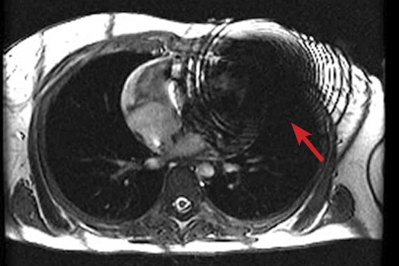
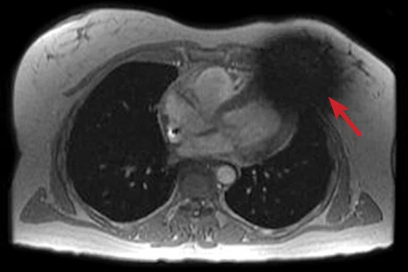
Figure 2.
(A) Axial FIESTA. (B) Axial Fast SPGR Cine post-contrast. Note the banding artifact in the FIESTA acquisition.
B
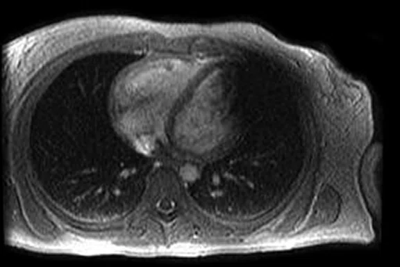
Figure 2.
(A) Axial FIESTA. (B) Axial Fast SPGR Cine post-contrast. Note the banding artifact in the FIESTA acquisition.
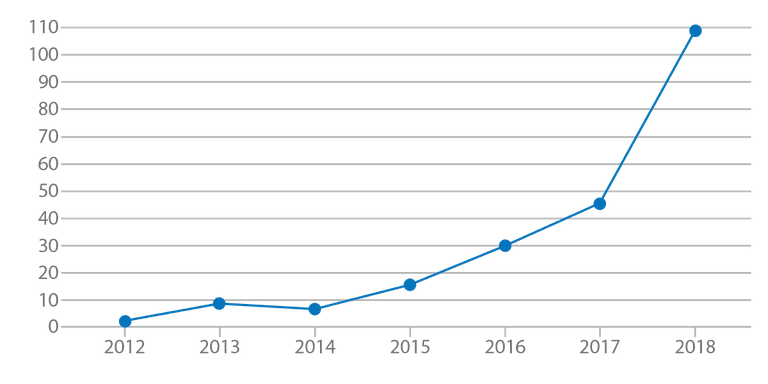
Figure 1.
Number of MR exams in patients with MR-Conditional devices, all types (cardiac and
non-cardiac) at the University of Wisconsin Hospital.
‡Drug products should be used in accordance with their approved labeling. Gadolinium-based contrast agents have not been approved for cardiac use in all regions.
A
Figure 3.
Acquired using Fast SPGR Cine. Comparison of a (A) conventional 8 mm thick/ 0 mm gap slice with a (B) 4 mm thickness and 4 mm spacing to maintain coverage. Note the decrease in artifact with the thinner slice imaging.
B
Figure 3.
Acquired using Fast SPGR Cine. Comparison of a (A) conventional 8 mm thick/ 0 mm gap slice with a (B) 4 mm thickness and 4 mm spacing to maintain coverage. Note the decrease in artifact with the thinner slice imaging.
A
Figure 4.
Comparison of (A, C) original inversion vs (B, D) higher broadband inversion, using the PSIR option. Note the improved image quality when improved broadband inversion was utilized.
B
Figure 4.
Comparison of (A, C) original inversion vs (B, D) higher broadband inversion, using the PSIR option. Note the improved image quality when improved broadband inversion was utilized.
C
Figure 4.
Comparison of (A, C) original inversion vs (B, D) higher broadband inversion, using the PSIR option. Note the improved image quality when improved broadband inversion was utilized.
D
Figure 4.
Comparison of (A, C) original inversion vs (B, D) higher broadband inversion, using the PSIR option. Note the improved image quality when improved broadband inversion was utilized.
A
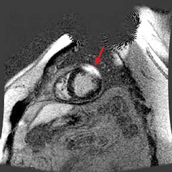
Figure 5.
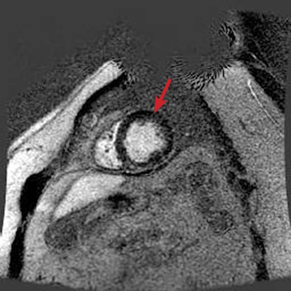
(A) Short axis Fast SPGR Cine; (B) long axis Fast SPGR Cine; (C) short axis MDE (arrow); (D-F) long axis MDE.
B
Figure 5.
(A) Short axis Fast SPGR Cine; (B) long axis Fast SPGR Cine; (C) short axis MDE (arrow); (D-F) long axis MDE.
C
Figure 5.
(A) Short axis Fast SPGR Cine; (B) long axis Fast SPGR Cine; (C) short axis MDE (arrow); (D-F) long axis MDE.
D
Figure 5.
(A) Short axis Fast SPGR Cine; (B) long axis Fast SPGR Cine; (C) short axis MDE (arrow); (D-F) long axis MDE.
E
Figure 5.
(A) Short axis Fast SPGR Cine; (B) long axis Fast SPGR Cine; (C) short axis MDE (arrow); (D-F) long axis MDE.
F
Figure 5.
(A) Short axis Fast SPGR Cine; (B) long axis Fast SPGR Cine; (C) short axis MDE (arrow); (D-F) long axis MDE.
A
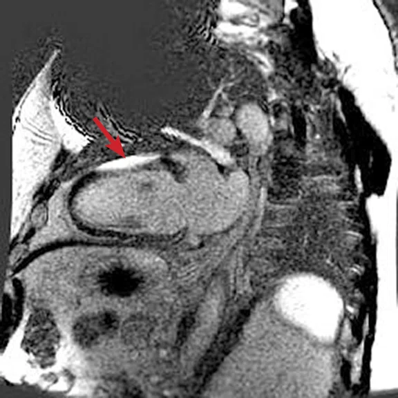
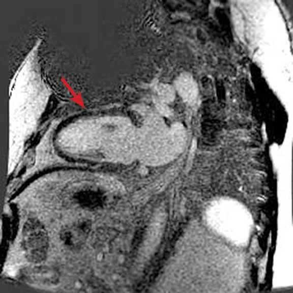
Figure 6.
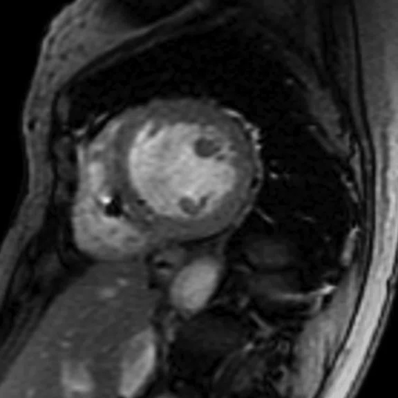
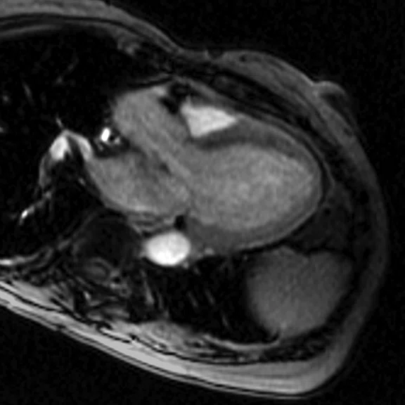
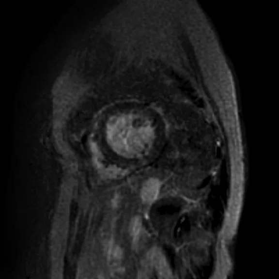
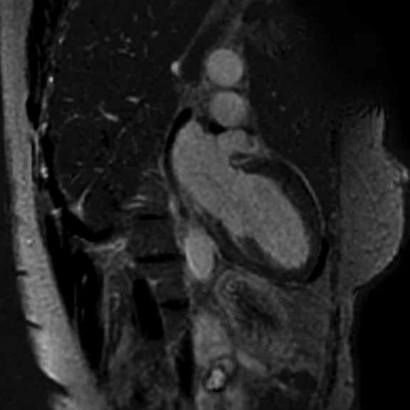
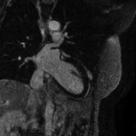
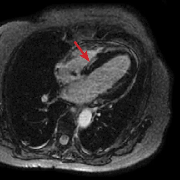
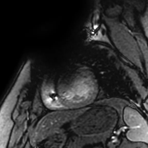
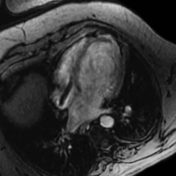
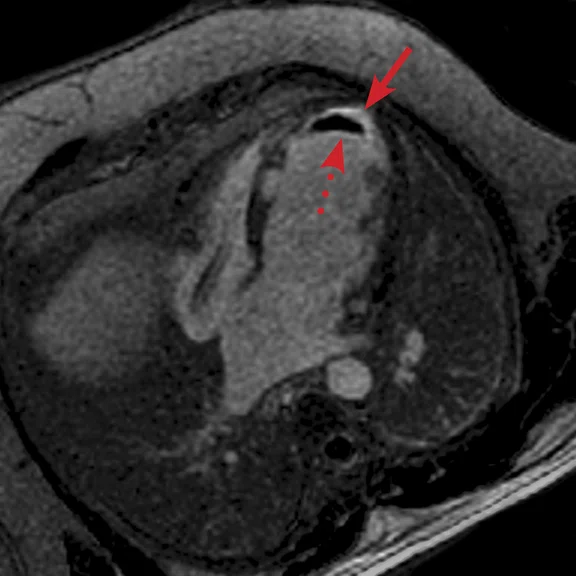
(A) Short axis Fast SPGR Cine; (B) long axis Fast SPGR Cine; (C-D) phase-sensitive long axis LGE.
B
Figure 6.
(A) Short axis Fast SPGR Cine; (B) long axis Fast SPGR Cine; (C-D) phase-sensitive long axis LGE.
C
Figure 6.
(A) Short axis Fast SPGR Cine; (B) long axis Fast SPGR Cine; (C-D) phase-sensitive long axis LGE.
D
Figure 6.
(A) Short axis Fast SPGR Cine; (B) long axis Fast SPGR Cine; (C-D) phase-sensitive long axis LGE.
result


PREVIOUS
${prev-page}
NEXT
${next-page}
Subscribe Now
Manage Subscription
FOLLOW US
Contact Us • Cookie Preferences • Privacy Policy • California Privacy PolicyDo Not Sell or Share My Personal Information • Terms & Conditions • Security
© 2024 GE HealthCare. GE is a trademark of General Electric Company. Used under trademark license.
IN PRACTICE
Cardiac MR in patients with CIEDs
Cardiac MR in patients with CIEDs
By Karl Vigen, PhD, Senior Scientist, and Christopher Francois, MD, Professor, University of Wisconsin Hospital, Madison, WI
MR imaging volume in patients with Cardiovascular Implantable Electronic Devices (CIEDs) is growing due to the adoption of MR-Conditional devices. Modified cardiac protocols can address common artifacts and distortions resulting from the device, battery or other electronic components, while also complying with MR-Conditional device labeling.
MR imaging volume in patients with Cardiovascular Implantable Electronic Devices (CIEDs) is growing due to the adoption of MR-Conditional devices. Modified cardiac protocols can address common artifacts and distortions resulting from the device, battery or other electronic components, while also complying with MR-Conditional device labeling.
MR imaging was historically contraindicated for patients with CIEDs including pacemakers, implantable cardioverter defibrillators (ICDs), and cardiac resynchronization therapy pacemakers and defibrillators (CRT-P/Ds), due to concerns over possible lead heating, device migration and device malfunction. However, recent CIED development has led to devices with improved resistance to environmental electromagnetic interference, and many recent models have MR-Conditional labeling with approval from regulatory agencies such as the FDA.
As more patients are implanted with MR-Conditional devices, our volumes have grown (see Figure 1) to more than 100 in 2018. The adoption of MR-Conditional implants improves access and the use of MR in these patient subgroups.
Due to the location of the CIED generator, most commonly in the left upper chest, distortions in B0 and B1 due to the battery and other electronic components can lead to severe artifacts in cardiac MR (CMR), particularly with ICDs and CRT-Ds. Nearly five years ago, our institution developed a modified CMR protocol for use in patients with CIEDs.
Prior to the imaging exam, a cardiac device nurse programs the patient’s device to the pacing parameters corresponding to the device’s "MRI mode" or another acceptable mode, as determined by the device clinic team. This is generally a setting such that pacing is off, or a backup mode such that the patient’s underlying rhythm is maintained. Occasionally, an asynchronous pacing mode can be used, which paces the patient’s heart at a regular rate, and can greatly improve MR image quality compared to an irregular heart rate.
Patient positioning in the MR scanner is similar to exams in patients without devices. The patient is connected to a patient monitoring system, so that the patient’s ECG and pulse oximetry information can be monitored throughout the exam. In addition, we attempt to have the patient place their arms over their head, as this can move the device away from the imaging field-of-view (FOV) and reduce the amount of main magnetic field (B0) modulation near the imaging FOV.
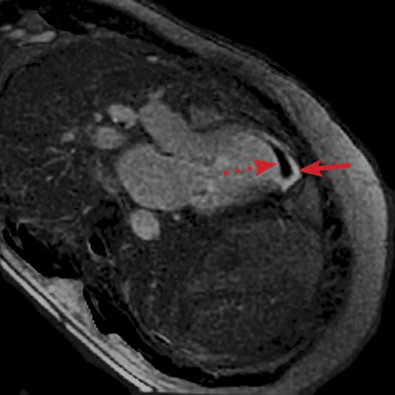
FIESTA imaging sequences can contain banding artifacts due to B0 field modulations; the artifacts can be particularly troubling due to the intense B0 modulation caused by the CIED. These artifacts are usually more severe with ICDs compared to pacemakers. By using a Fast SPGR Cine imaging sequence, the banding artifacts can be removed, albeit with a reduction of blood-to-myocardium contrast-to-noise ratio (CNR). Acquiring the short- and long-axis Fast SPGR Cine images following contrast agent administration can improve CNR, and has the additional benefit of decreasing total exam time (since there is normally 10 minutes of waiting following contrast agent administration).‡ Figure 2 shows a typical image acquired with FIESTA (2A) and post-contrast Fast SPGR Cine (2B) in a patient with an ICD.
Using thinner slices to reduce through-slice dephasing can also help reduce artifact. In Figure 3A, a more conventional 8 mm thick/0 mm gap slice was used with Axial post-contrast Fast SPGR Cine; in Figure 3B, a slice at the same location with 4 mm thickness and 4 mm spacing to maintain coverage with fewer artifacts was utilized. Disadvantages include increased TE with reduced slice thickness and reduced SNR, although the CNR between blood and myocardium can be improved if acquired post-contrast.
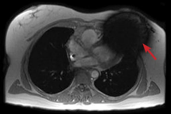
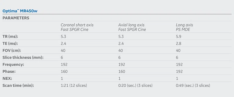
For late gadolinium enhanced (LGE)/myocardial delayed enhancement (MDE) imaging, an inversion pulse with an appropriate TI is used to suppress signal from normal myocardium, highlighting signal from infarcted myocardium. With conventional MDE imaging, B0 inhomogeneity could cause incomplete inversion and artifactual high signal in normal myocardium could be mistaken for infarction. A new wide-bandwidth adiabatic inversion pulse for MDE (standard in GE’s DV26.0 software) allows suppression of myocardial signal without artifactual high signal (see clinical cases). When combined with the Phase-Sensitive Inversion Recovery (PSIR) option, high image quality can be achieved (Figure 4). We do not use the single-shot MDE sequence (SS MDE) at 1.5T for these patients, since this uses a FIESTA readout combined with parallel imaging; the combination is prone to artifactual high late enhancing signal.
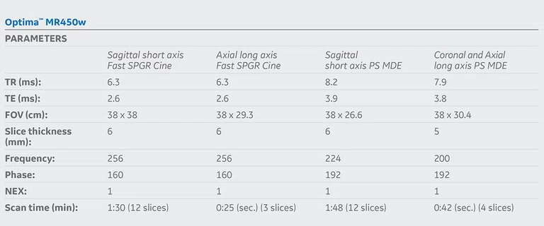
We image all MR-Conditional CIED patients at 1.5T, with SAR and dB/dT set to Normal Operating Mode, which has a whole body SAR limit of 2.0 W/kg. Recent versions of GE software include a Low SAR mode, allowing the user to specify even lower limits for SAR or B1+RMS. Most MR-Conditional CIEDs specify 2.0 W/kg for SAR at 1.5T; however, those that are MR-Conditional at 3.0T can have lower limits. For example, the Medtronic Advisa DR/SR MRI pacemakers specify maximum B1+RMS=2.8μT for thoracic imaging, which can be easily set in Low SAR mode. The availability of 3.0T imaging combined with low SAR mode is expected to be important if the scan is clinically indicated for 3.0T (e.g., PET/MR) or for institutions without access to a 1.5T system.
Currently, all patients with MR-Conditional CEIDs are scanned on a wide bore 1.5T MR system in our facility, assuming specifications for field strength and maximum spatial gradients of the static field in the MR-Conditional device labeling can be met. We find the wider bore is particularly helpful when imaging patients who cannot easily hold their arms above their head. Additionally, employing rapid sequences may reduce scan times and enhance patient comfort and compliance; however, our institution has not yet evaluated rapid sequences for CMR imaging in patients with MR-Conditional devices.
Recently, GE introduced lightweight AIR Technology™ Coils. While we have not had an opportunity to use the AIR Technology™ Coils for imaging patients with CIEDs, our current experience for cardiac imaging on our 3.0T SIGNA™ Premier systems demonstrate excellent image quality. We anticipate improved patient comfort for these exams, which may facilitate improved compliance for arms-above-head positioning.
Case 1
Patient with a history of dilated cardiomyopathy and worsening ejection fraction; pacing dependent. With MR, the left atrium and left ventricle were shown to be mildly dilated. Global hypokinesis was seen with regional variation specifically with focal hypokinesis/dyskinesis in the mid/apical septal and apical anterior segments. There is curvilinear late gadolinium enhancement consistent with scarring in the basal-anterior septal mid myocardium.
Case 2
Patient with a history of ventricular tachycardia with possible left ventricular thrombus. MR shows enlarged left ventricle, with global hypokinesis with dyskinesis in the apical anterior wall and true apex. Thrombus is seen in the apex, with a thin rim of increased enhancement at the edges of the thrombus. There is subendocardial to transmural enhancement in the apex.


