Technology in development that represents ongoing research and development efforts. These technologies are not products and may never become products. Not for sale. Not cleared or approved by the US FDA or any other global regulator for commercial availability. This article is about a prototype that is not the current technology in development and will not be commercialized.
A
Figure 1.
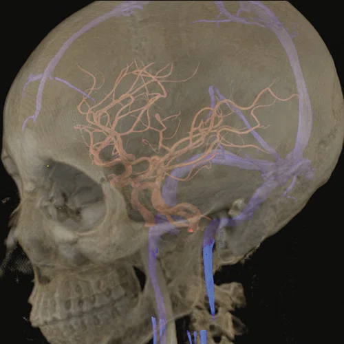
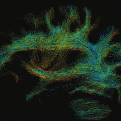
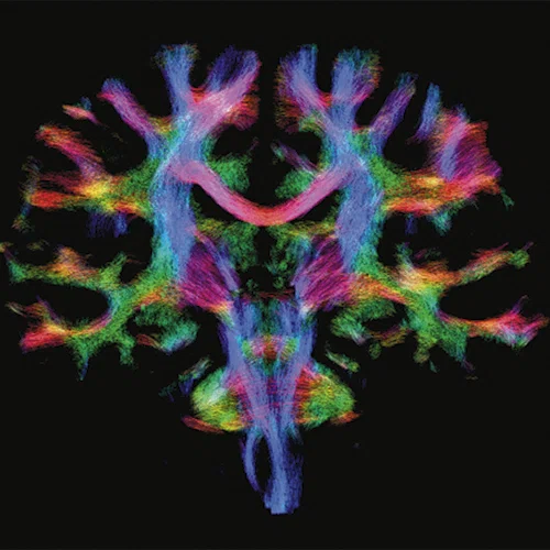
(A) Anatomical reference of bony structures using oZTEo, 1.0 x 1.0 x 1.0 mm, 3:16 min., with fusion to Inhance 3D Velocity, 0.8 x 0.9 x 1 mm, 45 cm/sec VENC, 3:10 min., and 3D time of flight (TOF) angiography, 0.4 x 0.4 x 0.5 mm. Image courtesy of University of Iowa. (B) Effective axonal radius map overlaid on brain tractograms, 5 shells total with b=9000, 14259, 19500, 24750, and 30000, 305 total directions, 2.2 x 2.2 x 2.2 mm. (C) Multi-shell diffusion tractography, 3 shells total with b=500, 2000, and 4000, 121 total directions, 1.5 x 1.5 x 1.5 mm.
B
Figure 1.
(A) Anatomical reference of bony structures using oZTEo, 1.0 x 1.0 x 1.0 mm, 3:16 min., with fusion to Inhance 3D Velocity, 0.8 x 0.9 x 1 mm, 45 cm/sec VENC, 3:10 min., and 3D time of flight (TOF) angiography, 0.4 x 0.4 x 0.5 mm. Image courtesy of University of Iowa. (B) Effective axonal radius map overlaid on brain tractograms, 5 shells total with b=9000, 14259, 19500, 24750, and 30000, 305 total directions, 2.2 x 2.2 x 2.2 mm. (C) Multi-shell diffusion tractography, 3 shells total with b=500, 2000, and 4000, 121 total directions, 1.5 x 1.5 x 1.5 mm.
C
Figure 1.
(A) Anatomical reference of bony structures using oZTEo, 1.0 x 1.0 x 1.0 mm, 3:16 min., with fusion to Inhance 3D Velocity, 0.8 x 0.9 x 1 mm, 45 cm/sec VENC, 3:10 min., and 3D time of flight (TOF) angiography, 0.4 x 0.4 x 0.5 mm. Image courtesy of University of Iowa. (B) Effective axonal radius map overlaid on brain tractograms, 5 shells total with b=9000, 14259, 19500, 24750, and 30000, 305 total directions, 2.2 x 2.2 x 2.2 mm. (C) Multi-shell diffusion tractography, 3 shells total with b=500, 2000, and 4000, 121 total directions, 1.5 x 1.5 x 1.5 mm.
‡ Technology in development that represents ongoing research and development efforts. These technologies are not products and may never become products. Not for sale. Not cleared or approved by the US FDA or any other global regulator for commercial availability. This article is about a prototype that is not the current technology in development and will not be commercialized.
A
Figure 2.
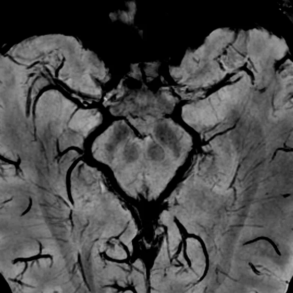
(A, B) 3D SWAN of the deep brain structures with phase mapping, 0.5 x 0.5 x 1 mm (3 mm MIP shown). (C) 3D TOF angiography, HyperSense 2.5, ARC 2, 0.4 x 0.4 x 0.5 mm, 6:01 min. (D) Axial 4D Flow, 145 cm/sec VENC, HyperKat 8, 1 x 1 x 1 mm, 6:19 min. Images courtesy of University of Iowa.
B
Figure 2.
(A, B) 3D SWAN of the deep brain structures with phase mapping, 0.5 x 0.5 x 1 mm (3 mm MIP shown). (C) 3D TOF angiography, HyperSense 2.5, ARC 2, 0.4 x 0.4 x 0.5 mm, 6:01 min. (D) Axial 4D Flow, 145 cm/sec VENC, HyperKat 8, 1 x 1 x 1 mm, 6:19 min. Images courtesy of University of Iowa.
C
Figure 2.
(A, B) 3D SWAN of the deep brain structures with phase mapping, 0.5 x 0.5 x 1 mm (3 mm MIP shown). (C) 3D TOF angiography, HyperSense 2.5, ARC 2, 0.4 x 0.4 x 0.5 mm, 6:01 min. (D) Axial 4D Flow, 145 cm/sec VENC, HyperKat 8, 1 x 1 x 1 mm, 6:19 min. Images courtesy of University of Iowa.
D
Figure 2.
(A, B) 3D SWAN of the deep brain structures with phase mapping, 0.5 x 0.5 x 1 mm (3 mm MIP shown). (C) 3D TOF angiography, HyperSense 2.5, ARC 2, 0.4 x 0.4 x 0.5 mm, 6:01 min. (D) Axial 4D Flow, 145 cm/sec VENC, HyperKat 8, 1 x 1 x 1 mm, 6:19 min. Images courtesy of University of Iowa.
‡ Technology in development that represents ongoing research and development efforts. These technologies are not products and may never become products. Not for sale. Not cleared or approved by the US FDA or any other global regulator for commercial availability. This article is about a prototype that is not the current technology in development and will not be commercialized.
1. Wiesinger F, Menini A, Solana AB. Looping Star. Magn Reson Med. 2019 Jan;81(1):57-68.
result


PREVIOUS
${prev-page}
NEXT
${next-page}
Subscribe Now
Manage Subscription
FOLLOW US
Contact Us • Cookie Preferences • Privacy Policy • California Privacy PolicyDo Not Sell or Share My Personal Information • Terms & Conditions • Security
© 2024 GE HealthCare. GE is a trademark of General Electric Company. Used under trademark license.
Tech Trends
Dedicated neuro MR imaging with MAGNUS
Dedicated neuro MR imaging with MAGNUS
"Now this is not the end. It is not even the beginning of the end. But it is, perhaps, the end of the beginning."
Sir Winston Churchill, November 1942
MAGNUS‡ (Mesoscale diffusion with Advanced Gradients for Neuro Ultrafast Scanning) is a high-performance MR gradient platform designed to produce high-quality images that characterize brain microstructure and function. Specifically, MAGNUS enables ultra-high b-value diffusion imaging with significantly higher signal-to-noise ratio (SNR) from shorter echo times, and functional MRI (fMRI) with less distortion from shorter echo spacings. This enhanced performance is possible because MAGNUS was designed to be one of the world’s most power-efficient head-only gradient coils with a significantly higher peripheral nerve stimulation threshold compared to whole-body scanners.
MAGNUS originated as a collaboration between GE HealthCare’s Technology & Innovation Center (HTIC), formerly GE Global Research Center, and the Uniformed Services University of the Health Sciences (USU). It was led by Thomas Foo, PhD, Chief Scientist at HTIC, and Vincent Ho, MD, Chair and Professor of the Department of Radiology at USU and Director of Research for the Department of Radiology at Walter Reed National Military Medical Center.
Dr. Foo and Dr. Ho worked together at the National Institute of Health (NIH) in the mid-1990s and shared a common interest in head-only 3.0T MR platforms.
“We wanted to have greater performance that was much higher than what was existing at that time,” Dr. Foo says. This included significantly increasing the maximum gradient amplitude and slew rate.
In 2010, an NIH grant provided the funding for Dr. Foo and Matt Bernstein, PhD, and John Huston, MD, both from Mayo Clinic (Rochester, MN) to pursue development of a low-cryogen, high-performance, head-only compact 3.0T MR scanner.‡ In 2016, this small head-only 3.0T MR scanner was installed at Mayo Clinic (Rochester, MN). That scanner attained a maximum gradient amplitude of 80 mT/m and was capable of acquiring echo planar images (EPI) at a gradient slew rate of 700 T/m/s. The extremely high slew rate was possible because the peripheral nerve stimulation threshold of head-only gradients is much higher than that of whole-body gradients, which allowed significantly more of the gradient performance specification to be used for imaging. Yet, it became apparent that to probe brain microstructure more extensively with diffusion imaging, significantly higher maximum gradient amplitudes were needed.
After further discussions with other MR scientists and colleagues, Dr. Foo and colleagues at HTIC decided to pursue the concept of a high-efficiency, high-performance head gradient that could be inserted into most whole-body magnets. This gradient coil would then be able to produce very high gradient amplitudes for diffusion imaging and very high slew rates for fMRI using the same subsystems in clinical whole-body scanners.
“This idea to develop a system for better diffusion and fMRI was conceived at the same time as the GE-NFL initiative on traumatic brain injuries,” Dr. Foo explains. (In 2013, GE and the National Football League [NFL] teamed up to launch the Head Health Initiative, a four-year, $60 million collaboration to accelerate diagnosis and improve treatment for traumatic brain injury.) “We thought that by looking at the brain microstructure in higher detail, and examining axonal diameter changes, we could achieve a breakthrough. However, this is only possible with high-performance gradients that can be used in humans.”
The HTIC team shared their concept with Dr. Ho and together they approached the Joint Program Committee 6 (JPC-6) Combat Casualty Care section of the Department of Defense (DOD) and secured funding for the project. In addition to Dr. Foo, some of the key GE HealthCare contributors to the project include: Nastaren Abad, PhD, Lead Scientist; Seung-Kyun Lee, PhD, Principal Scientist; Justin Ricci, MS, Senior Engineer; Ante Zhu, PhD, Lead Scientist; Yihe Hua, PhD, Senior Scientist; and Desmond Teck Beng Yeo, PhD, MBA, Technology Manager, MRI & Superconducting Magnets.
Figure 1.
(A) Anatomical reference of bony structures using oZTEo, 1.0 x 1.0 x 1.0 mm, 3:16 min., with fusion to Inhance 3D Velocity, 0.8 x 0.9 x 1 mm, 45 cm/sec VENC, 3:10 min., and 3D time of flight (TOF) angiography, 0.4 x 0.4 x 0.5 mm. Image courtesy of University of Iowa. (B) Effective axonal radius map overlaid on brain tractograms, 5 shells total with b=9000, 14259, 19500, 24750, and 30000, 305 total directions, 2.2 x 2.2 x 2.2 mm. (C) Multi-shell diffusion tractography, 3 shells total with b=500, 2000, and 4000, 121 total directions, 1.5 x 1.5 x 1.5 mm.
Rethinking gradient design
“One key design decision that we made was the patient access space dimensions,” Dr. Lee says. “We have a 42 cm internal diameter for the MAGNUS gradient coil, which comes from the compact 3.0T system that was installed at Mayo Clinic. That was important because prior to the compact 3.0T, a lot of head-only systems had a much smaller internal diameter, targeting a smaller field-of-view that was typically 22 cm.”
The target field of view (FOV) was 26 cm, which is sufficient to accommodate a commercially available multi-channel receiver array head coil. Within this FOV, the system could capture the entire head and a significant portion of the neck without distortion, and benefit from the acceleration made possible by a high-channel count receiver array.
In addition to providing the potential to visualize the anatomy with exceptional clarity, the design had to be highly power-efficient so that the gradient platform could be utilized in existing clinical MR systems.
While the low-cryogen compact 3.0T scanner filled a need for brain-only imaging, particularly in settings with magnet siting requirements not conducive to conventional whole-body scanners, the team wanted to “achieve high-performance brain imaging in existing whole-body clinical scanners without a need to elevate the siting requirements,” says Dr. Yeo.
“A core design feature of MAGNUS is its ability to be inserted into most 3.0T whole-body systems. That feature is also an enabler of MAGNUS’ high-power efficiency, as a wider magnet bore enables a wider gap between the primary and shield gradient coil layers, which increases the efficiency of the gradient coil and generates a much higher gradient amplitude for the same applied current,” Dr. Yeo adds. That meant that most existing (installed) and new 3.0T whole-body magnets could potentially be transformed into high-performance brain imaging scanners with minimal changes to siting and infrastructure requirements. As an example, the siting requirements for a system like SIGNA™ Premier XT and MAGNUS are the same, and existing SIGNA™ Premier XT systems can be upgraded to MAGNUS once regulatory clearances are received.‡
The scalability of MAGNUS’ gradient performance is also its strength. “MAGNUS was designed with scalable performance in mind, without modification to its coil design or penalties of spatial distortion and signal loss. The MAGNUS design concept was to accommodate both today’s and tomorrow’s MR applications, without the need to modify the coil’s design or construction. This means that as new pulse sequences and improvements are implemented, MAGNUS will continue to deliver the same high performance and clinical benefits,” says Dr. Abad.
As gradient driver technology improved (from 1 MVA to 2 MVA standard clinical gradient drivers), the team was able to increase the maximum gradient performance by 1.5x from 200 mT/m and 500 T/m/s (at 1 MVA) to 300 mT/m and 750 T/m/s (2 MVA). The MAGNUS design has sufficient thermal margin to accommodate even higher-powered gradient drivers in the future.
MAGNUS utilizes asymmetric gradients to shift the FOV away from its isocenter, towards the patient end of the gradient. This design feature enables a head to be imaged without requiring a large-diameter gradient that would have drastically increased power requirements. While asymmetric gradients are not a new concept in MR, in some earlier asymmetric gradient designs, certain critical head regions were not clearly visible.
“We had to be able to visualize the frontal lobe, cerebellum and down to the third cervical spine without distortion,” says Dr. Foo.
The asymmetric design will also enable subjects to be scanned with higher slew rates. By shifting the FOV to one end of the gradient bore, the asymmetric design reduces the exposed length of a body (just the head and neck) to fast-switching magnetic fields. Since it is much harder to electrically stimulate the head than the rest of the body with these switching fields, the peripheral nerve stimulation threshold in MAGNUS is much higher than whole-body gradient coils, and thus, higher gradient slew rates can be utilized to improve imaging performance.
“The asymmetric gradient design allows us to use high amplitude and slew rate that are available from the hardware,” says Dr. Lee. “Because in a symmetric design, even if the hardware can handle the high-performance specification, the patient cannot.”
Imaging the microstructure
With the power of MAGNUS, it is expected that users can acquire and extract more specific information about brain microstructure, circuits and function that could not be obtained on a conventional whole-body system. These include information about axonal radii for neurodegenerative disease diagnosis and neuroplasticity, glymphatic circulation in sleep disorders, cellularity of tumors for cancer grading, cell packing and extra-axonal space changes.
“The parallel structural and functional gains available with this system design will allow for a comprehensive understanding of the brain – and we are just beginning to scratch the surface on the possibilities,” says Dr. Abad. “The increased gradient amplitudes allow for expanded diffusion capabilities to measure length scales that are more representative of underlying microstructure. Meanwhile, fast slew rates will translate to faster readouts, shorter pulse widths, decreased distortion and higher temporal resolution.”
Dr. Abad explains that from a fMRI perspective, advanced techniques such as multi-echo EPI can be used to increase sensitivity to differentiate between blood oxygenation level dependent (BOLD) versus non-BOLD signal sources. The sequence can be modeled such that the user can optimize the number of echoes and echo spacing with minimal to no impact on the repetition times (TR) of scans. In the same thread, conventional protocols leveraging single-echo EPI for BOLD contrast also benefit. For example, whole-brain scans with a TR of 500 ms may become possible. The advantages are anticipated not just for Cartesian imaging/EPI; non-Cartesian trajectories may also benefit. The team has been exploring with collaborators at USU and GE HealthCare scientists Ana Beatriz Solana Sánchez, PhD, and Florian Wiesinger, PhD, the potential for silent fMRI using the novel Looping Star‡ technique.1 MAGNUS is integrated with a local transmit birdcage coil that results in a higher peak B1+, allowing for higher transmit efficiency and lower whole-body specific absorption rate (SAR).
“It’s not just the gradient design that drives performance, rather there is also the RF design that will help deliver the performance,” adds Dr. Abad.
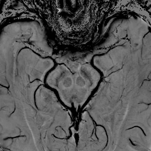
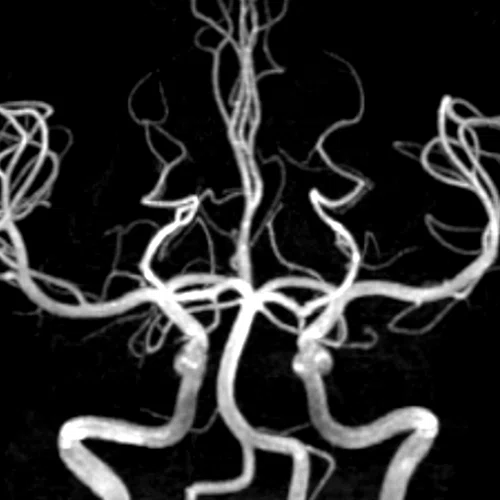
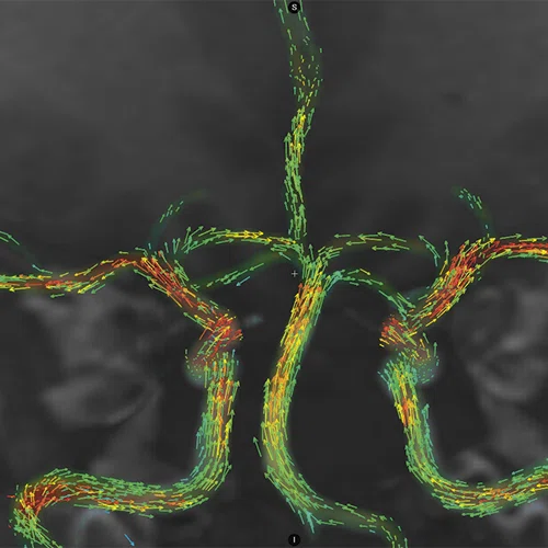
Figure 2.
(A, B) 3D SWAN of the deep brain structures with phase mapping, 0.5 x 0.5 x 1 mm (3 mm MIP shown). (C) 3D TOF angiography, HyperSense 2.5, ARC 2, 0.4 x 0.4 x 0.5 mm, 6:01 min. (D) Axial 4D Flow, 145 cm/sec VENC, HyperKat 8, 1 x 1 x 1 mm, 6:19 min. Images courtesy of University of Iowa.
Pursuing innovation
From the beginning, there was potential for the DOD/NIH/GE HealthCare head-only 3.0T MR initiative to succeed where
others had failed.
“It was a risky endeavor; however, the proof of concept was accepted by key opinion leaders,” says Dr. Foo.
Drs. Foo and Ho had the benefit of learning from prior published studies and research efforts and saw where these projects fell short, mainly that the hardware platform performance remained the same. There had to be a step change in performance to affect the change in clinical results.
Because the project was a collaboration between government and industry research, the team had the support to pursue innovation and not be constrained by a short-term, singular goal to develop a new product.
“At HTIC, we encourage our team to explore and pursue knowledge and innovation, and to cross the boundaries of disciplines, sub-systems and modalities, when needed,” says Dr. Yeo. “We want our scientists to look further out and find the highest impact ideas for the long-term, and then act on the best ones. We are also fortunate to have a dedicated team of non-technical support staff in environmental health and safety, legal, IT, finance, etc., whose primary mission is to support researchers and to break down barriers with, and for, them. These are critical elements for success when pursuing long-range, high-risk and high-reward research.”
The first MAGNUS was installed at Walter Reed National Military Medical Center in early 2020. Then, the COVID pandemic hit in March 2020, and only medical personnel and patients were allowed on site at Walter Reed.
Fortunately, the team could remotely operate the MAGNUS system to optimize protocols. For the next six to eight months, Drs. Abad and Foo and the rest of the team remotely tested system performance and scanned volunteers – medical personnel and residents at Walter Reed – on the MAGNUS system.
“It was a testament to the flexibility of our systems, the architecture and the healthcare system that allowed us to interact with the technologists remotely to scan on MAGNUS during the pandemic closures,” Dr. Foo says.
Soon, the industry began to learn about the research-based MAGNUS system and its impressive imaging capabilities through presentations at conferences and published papers. The University of Iowa and University of Wisconsin-Madison both obtained NIH high-end instrumentation grants to acquire the next two MAGNUS systems, followed by Brigham and Women’s Hospital, which obtained support from the Massachusetts Life Sciences Center.
Based on the success of the MAGNUS installation at Walter Reed National Military Medical Center, and the interest in the system from other leading academic and research sites, GE HealthCare’s MR business leadership determined that there was sufficient evidence to proceed with commercializing this innovative, head-only research-based MR imaging technology.
“It wasn’t that difficult to persuade leadership, all we had to do was outline the unmet needs of MR neuroscientists and to show the images acquired by MAGNUS,” says Dr. Foo. “They had not seen images like that before, and the possibilities of this technology became clear.”
The team performed comparison studies between whole-body MR and MAGNUS, and the quality was like night and day.
Dr. Foo compares it to the difference between standard definition and high-definition televisions, where the former is grainy and the latter is crisp and detailed.
“MAGNUS has exceeded my expectations,” says Dr. Foo. “I wasn’t expecting the exceptional quality, but these images are brilliant.”
MAGNUS is designed to further propel neuroscience discovery/developments in the clinical setting, such as in neurodegenerative diseases, psychiatry, traumatic brain injuries, neurological development and stroke rehabilitation.
“The whole concept of neuroplasticity and how the brain rewires is fascinating,” says Dr. Foo. “We know the brain adapts to disease and injury, yet we are not able to track and measure it. The potential to do that with MAGNUS by looking at the microstructural changes, both in the gray and white matter, and obtaining that complete picture was one of the key motivating factors behind the development of this system.”
“MAGNUS is just beginning its journey in impacting the clinical neuroscience realm,” adds Dr. Yeo. “As that happens, we are working on new avenues to make the performance of MAGNUS even better.”
DOWNLOAD ARTICLE HERE


