A
Figure 1.
Prostate exam with AIR™ Recon DL. (A) Axial T2w, (B) axial FOCUS DWI b800, (C) ADC Map, (D-G) series of acquired 2.4 x 2.4 x 2 mm slices.
B
Figure 1.
Prostate exam with AIR™ Recon DL. (A) Axial T2w, (B) axial FOCUS DWI b800, (C) ADC Map, (D-G) series of acquired 2.4 x 2.4 x 2 mm slices.
C
Figure 1.
Prostate exam with AIR™ Recon DL. (A) Axial T2w, (B) axial FOCUS DWI b800, (C) ADC Map, (D-G) series of acquired 2.4 x 2.4 x 2 mm slices.
D
Figure 1.
Prostate exam with AIR™ Recon DL. (A) Axial T2w, (B) axial FOCUS DWI b800, (C) ADC Map, (D-G) series of acquired 2.4 x 2.4 x 2 mm slices.
E
Figure 1.
Prostate exam with AIR™ Recon DL. (A) Axial T2w, (B) axial FOCUS DWI b800, (C) ADC Map, (D-G) series of acquired 2.4 x 2.4 x 2 mm slices.
F
Figure 1.
Prostate exam with AIR™ Recon DL. (A) Axial T2w, (B) axial FOCUS DWI b800, (C) ADC Map, (D-G) series of acquired 2.4 x 2.4 x 2 mm slices.
G
Figure 1.
Prostate exam with AIR™ Recon DL. (A) Axial T2w, (B) axial FOCUS DWI b800, (C) ADC Map, (D-G) series of acquired 2.4 x 2.4 x 2 mm slices.
A-1
Figure 3.
Lumbar spine exam with (A) oZTEo, 1.3 x 1.3 x 1.3 mm, 4:09 min., depicting an osteophyte formation. Using AIR™ Recon DL, (B) sagittal STIR, 0.8 x 1.1 x 2.5 mm, 2:46 min.; (C) sagittal T2w, 0.6 x 0.7 x 2.5 mm, 2:57 min.; and (D) sagittal T1w 1.1 x 1.5 x 2.5 mm, 3:02 min.
B
Figure 3.
Lumbar spine exam with (A) oZTEo, 1.3 x 1.3 x 1.3 mm, 4:09 min., depicting an osteophyte formation. Using AIR™ Recon DL, (B) sagittal STIR, 0.8 x 1.1 x 2.5 mm, 2:46 min.; (C) sagittal T2w, 0.6 x 0.7 x 2.5 mm, 2:57 min.; and (D) sagittal T1w 1.1 x 1.5 x 2.5 mm, 3:02 min.
C
Figure 3.
Lumbar spine exam with (A) oZTEo, 1.3 x 1.3 x 1.3 mm, 4:09 min., depicting an osteophyte formation. Using AIR™ Recon DL, (B) sagittal STIR, 0.8 x 1.1 x 2.5 mm, 2:46 min.; (C) sagittal T2w, 0.6 x 0.7 x 2.5 mm, 2:57 min.; and (D) sagittal T1w 1.1 x 1.5 x 2.5 mm, 3:02 min.
D
Figure 3.
Lumbar spine exam with (A) oZTEo, 1.3 x 1.3 x 1.3 mm, 4:09 min., depicting an osteophyte formation. Using AIR™ Recon DL, (B) sagittal STIR, 0.8 x 1.1 x 2.5 mm, 2:46 min.; (C) sagittal T2w, 0.6 x 0.7 x 2.5 mm, 2:57 min.; and (D) sagittal T1w 1.1 x 1.5 x 2.5 mm, 3:02 min.
A-2
Figure 3.
Lumbar spine exam with (A) oZTEo, 1.3 x 1.3 x 1.3 mm, 4:09 min., depicting an osteophyte formation. Using AIR™ Recon DL, (B) sagittal STIR, 0.8 x 1.1 x 2.5 mm, 2:46 min.; (C) sagittal T2w, 0.6 x 0.7 x 2.5 mm, 2:57 min.; and (D) sagittal T1w 1.1 x 1.5 x 2.5 mm, 3:02 min.
A
Figure 4.
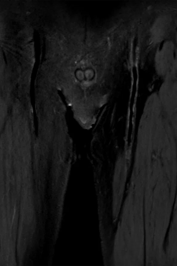
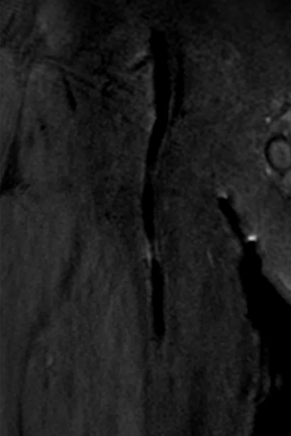
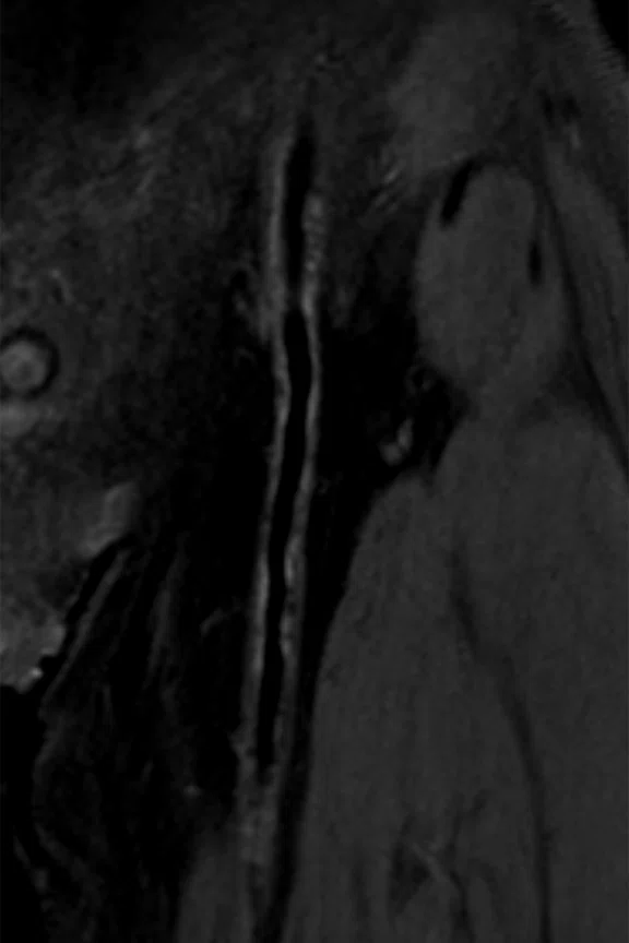
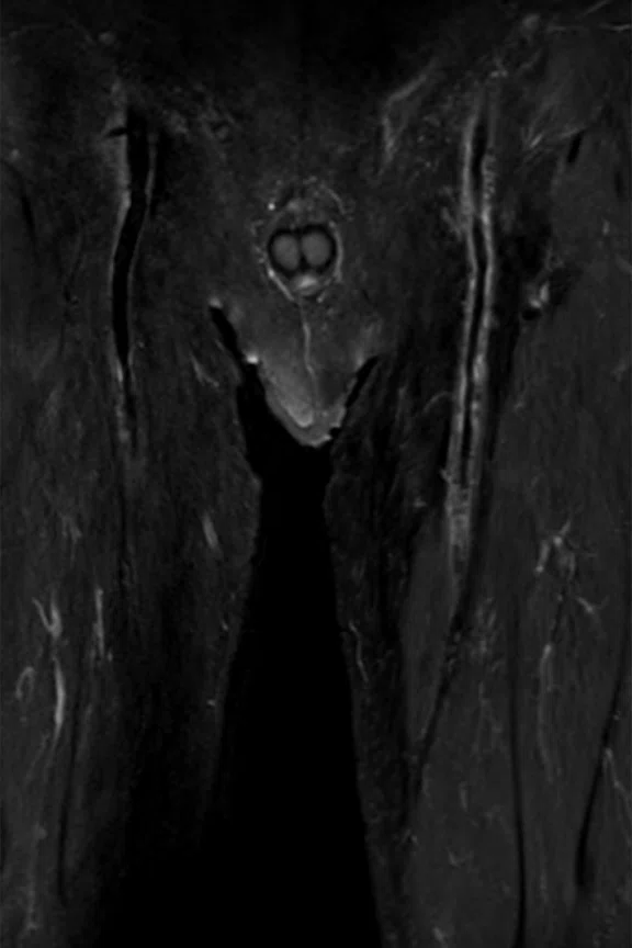
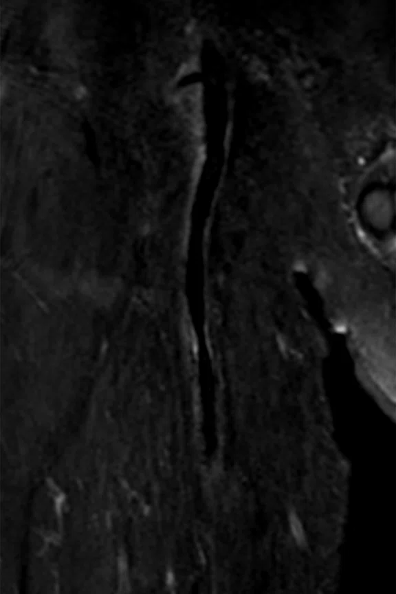
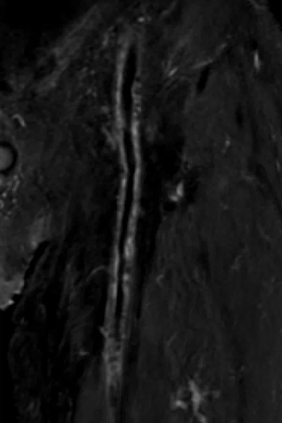
Black blood MR angiography of the femur using Cube MSDE, 0.9 x 0.9 x 0.6 mm, 5:15 min. (A) Pre-contrast acquisition confirmed plaque on the vascular wall of the left femoral artery, (B, C) magnified (A); and (D) post-contrast acquisition confirmed vessel wall enhancement, (E, F) magnified (D).
B
Figure 4.
Black blood MR angiography of the femur using Cube MSDE, 0.9 x 0.9 x 0.6 mm, 5:15 min. (A) Pre-contrast acquisition confirmed plaque on the vascular wall of the left femoral artery, (B, C) magnified (A); and (D) post-contrast acquisition confirmed vessel wall enhancement, (E, F) magnified (D).
C
Figure 4.
Black blood MR angiography of the femur using Cube MSDE, 0.9 x 0.9 x 0.6 mm, 5:15 min. (A) Pre-contrast acquisition confirmed plaque on the vascular wall of the left femoral artery, (B, C) magnified (A); and (D) post-contrast acquisition confirmed vessel wall enhancement, (E, F) magnified (D).
D
Figure 4.
Black blood MR angiography of the femur using Cube MSDE, 0.9 x 0.9 x 0.6 mm, 5:15 min. (A) Pre-contrast acquisition confirmed plaque on the vascular wall of the left femoral artery, (B, C) magnified (A); and (D) post-contrast acquisition confirmed vessel wall enhancement, (E, F) magnified (D).
E
Figure 4.
Black blood MR angiography of the femur using Cube MSDE, 0.9 x 0.9 x 0.6 mm, 5:15 min. (A) Pre-contrast acquisition confirmed plaque on the vascular wall of the left femoral artery, (B, C) magnified (A); and (D) post-contrast acquisition confirmed vessel wall enhancement, (E, F) magnified (D).
F
Figure 4.
Black blood MR angiography of the femur using Cube MSDE, 0.9 x 0.9 x 0.6 mm, 5:15 min. (A) Pre-contrast acquisition confirmed plaque on the vascular wall of the left femoral artery, (B, C) magnified (A); and (D) post-contrast acquisition confirmed vessel wall enhancement, (E, F) magnified (D).
A
Figure 2.
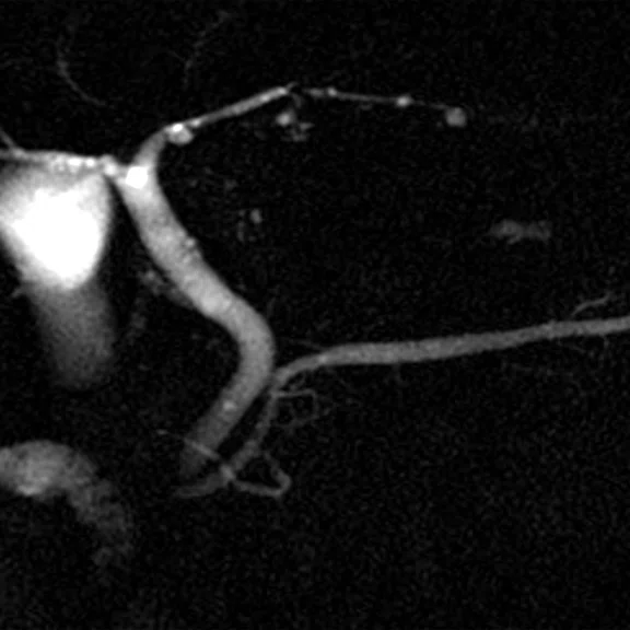
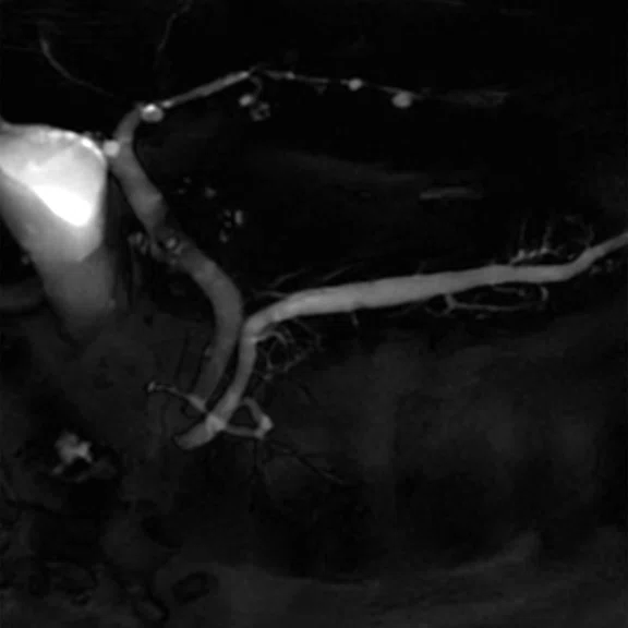
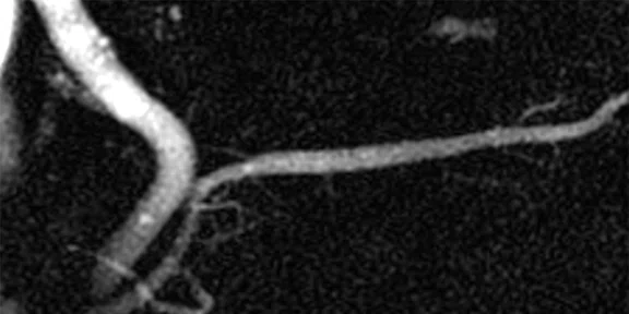
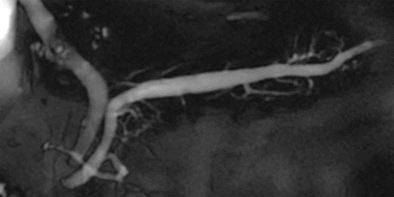
(A) Conventional 2D MRCP acquisition (122.07 Hz/pixel) compared to (B) 2D MRCP with AIR™ Recon DL (390.625 Hz/pixel).
B
Figure 2.
(A) Conventional 2D MRCP acquisition (122.07 Hz/pixel) compared to (B) 2D MRCP with AIR™ Recon DL (390.625 Hz/pixel).
A
Figure 2.
(A) Conventional 2D MRCP acquisition (122.07 Hz/pixel) compared to (B) 2D MRCP with AIR™ Recon DL (390.625 Hz/pixel).
B
Figure 2.
(A) Conventional 2D MRCP acquisition (122.07 Hz/pixel) compared to (B) 2D MRCP with AIR™ Recon DL (390.625 Hz/pixel).
A
Figure 2.
(A) Conventional 2D MRCP acquisition (122.07 Hz/pixel) compared to (B) 2D MRCP with AIR™ Recon DL (390.625 Hz/pixel).
A
Figure 2.
(A) Conventional 2D MRCP acquisition (122.07 Hz/pixel) compared to (B) 2D MRCP with AIR™ Recon DL (390.625 Hz/pixel).
B
Figure 2.
(A) Conventional 2D MRCP acquisition (122.07 Hz/pixel) compared to (B) 2D MRCP with AIR™ Recon DL (390.625 Hz/pixel).
B
Figure 2.
(A) Conventional 2D MRCP acquisition (122.07 Hz/pixel) compared to (B) 2D MRCP with AIR™ Recon DL (390.625 Hz/pixel).


result
PREVIOUS
${prev-page}
NEXT
${next-page}
Subscribe Now
Manage Subscription
FOLLOW US
Contact Us • Cookie Preferences • Privacy Policy • California Privacy PolicyDo Not Sell or Share My Personal Information • Terms & Conditions • Security
© 2024 GE HealthCare. GE is a trademark of General Electric Company. Used under trademark license.
IN PRACTICE
Maintaining image quality with shorter scan times improves productivity
Maintaining image quality with shorter scan times improves productivity
At Japan’s oldest private medical school, pioneering technology delivers high-quality images with fast scans to ensure patients’ comfort.
At Japan’s oldest private medical school, pioneering technology delivers high-quality images with fast scans to ensure patients’ comfort.
Nippon Medical School has 140 years of history ensuring its graduates are guided by its two founding principles: Saisei-Kyumin (to save people everywhere) and Kokki-Junko (to dedicate oneself to public service).
The Nippon Medical School Musashi Kosugi Hospital in Kawasaki, Japan, installed the SIGNA™ Pioneer to help uphold these values. Tetsuro Sekine, MD, PhD, at Nippon Medical School Musashi Kosugi Hospital, said the hospital chose the SIGNA™ Pioneer because it offers the AIR™ family of products, including AIR™ Coils and AIR™ Recon DL.
He credits the AIR™ Coils with significantly improving the quality of exams, especially critical T2-weighted images in abdominal exams. The 48-channel Head Coil greatly improves the image quality of brain exams.
“When purchasing a new MR system, we needed a model that supports deep-learning reconstruction techniques. In addition, we wanted to utilize the AIR™ Coils,” he explains.
AIR™ Recon DL makes the difference
The hospital is using AIR™ Recon DL on all MR imaging studies where it can be used to simultaneously reduce scan time and improve exam quality, particularly in prostate, brain/spine, and upper abdomen exams.
“The major clinical benefits are thin slice imaging and improved SNR, as well as a reduction in scanning time. These benefits are seen in scans across all anatomies, sequences or parameters where we can use this technology. AIR™ Recon DL eliminates frustration with conventional MR because it allows us to set parameters for higher resolution or shorter imaging time, so we can adapt the acquisition to the patient and the clinical question,” says Dr. Sekine.
In prostate imaging, AIR™ Recon DL has dramatically improved SNR in T2-weighted images and images obtained with DWI, while decreasing scan time (Figure 1). It has also allowed the hospital to obtain thinner slices. “AIR™ Recon DL allows us to achieve an extremely thin slice of 2 mm, which is very useful for detecting low-signal areas within the faint signal area in the prostate. The reduction of the partial volume effect results in clear contrast and high-value clinical images. Furthermore, thin slice imaging can provide images with sufficient SNR in the same amount of time as conventional examinations.”
In neuro scans, they were able to modify the routine protocol to a slice thickness of 3-4 mm, which is thinner than what was used previously. “The improvement in diagnostic performance due to the improvement in SNR may be small, but the scanning time is slightly shortened.”
This also allowed them to update their sagittal spine protocol to utilize 2.5 mm slices, helping them better visualize the microstructure of the intervertebral foramen where the nerve root emerges. “The number of slices is increased, but with AIR™ Recon DL you can cover the range in the same amount of time as conventional scans. I like the improved SNR of the conventional T2-weighted images in the spine, which allows me to better see fat and soft tissue.”
AIR™ Recon DL also improved imaging of the upper abdomen with single shot FSE. The thinner slices and high bandwidth enabled by AIR™ Recon DL have directly impacted patients who can’t hold their breath during the scan, such as during a 2D MR cholangiopancreatography (MRCP) exam (Figure 2). As a result, they obtained sharp images of the bile and pancreatic ducts. In addition, they could clearly see the morphology of the main pancreatic duct and accessory pancreatic duct. “In order to diagnose early pancreatic cancer, it’s necessary to accurately detect the presence or absence of detail stenosis or dilation in the pancreatic duct, so it’s very useful for diagnosing,” says Dr. Sekine.
The shorter exams have improved workflow and productivity in the MR suite by allowing for additional acquisitions, when needed, in a typical 20-minute time slot. For example, during brain exams it’s sometimes necessary to add 4D Flow or 3D sequences. In the upper abdomen, additional imaging may be performed to visualize the flow of pancreatic fluid. “Even if special additional imaging is obtained, we can complete it within the scheduled reservation slot,” he says. They can also reduce the number of time slots needed for certain exams, such as reducing MRCP scans from two slots to just one.
In addition, it reduces the burden of image interpretation on radiologists, as they no longer need to remove the noise from images to assess anatomy. The higher SNR has improved the radiologists’ diagnostic confidence, even in challenging anatomies or cases. “In every anatomical region, we are more confident in our diagnostic ability, particularly when evaluating fine structures,” Dr. Sekine adds.
oZTEo improves bone and soft tissue contrast
The SIGNA™ Pioneer enables oZTEo, a new application that provides enhanced cortical bone versus soft tissue contrast in MR. Based on the radial zero echo-time (ZTE) application, oZTEo allows facilities to be a one-stop shop for orthopedic imaging and add considerable clinical value to orthopedic exams. oZTEo is inherently motion-insensitive and complements a conventional MR soft tissue exam to deliver 3D isotropic imaging with familiar bright bone contrast.
At Nippon Medical School Musashi Kosugi Hospital, this eliminates the need to align CT and MR scans to visualize these structures. “oZTEo is extremely useful in improving workflow in a series of exams. Being able to make diagnoses with MR with perfectly aligned bones and soft tissue makes clinical workflow simple,” he says.
Adding oZTEo to an MR exam increases diagnostic confidence. For example, it can deliver clear answers for patients with lumbar spine pain (Figure 3). “The bone information from oZTEo is unexpectedly useful for diagnosis,” he says.
Dr. Sekine expects oZTEo to help them identify osteophyte formation to diagnose knee osteoarthritis. “I think that combining quantitative mapping such as T2 mapping with cartilage diagnosis will be extremely useful. Bone information is very important to orthopedic surgeons, so I think that MR bone imaging will become an important imaging method in the future,” adds Dr. Sekine.
MSDE for body imaging
In black blood imaging, the Motion-Sensitized Driven-Equilibrium (MSDE) sequence can visualize the anatomical structure of blood vessels, including the blood vessel wall and outer lumen. However, conventional black blood imaging requires a lengthy imaging time. The MDSE sequence can mitigate this challenge. They use Cube T1 with MSDE for pre- and post-contrast enhancement examination (Figure 4). “The greatest advantage of MSDE is there’s no residual blood in the lumen of the blood vessel due to contrast-enhanced T1 weighting, and it provides stable image quality,” he says.
Figure 4.
Black blood MR angiography of the femur using Cube MSDE, 0.9 x 0.9 x 0.6 mm, 5:15 min. (A) Pre-contrast acquisition confirmed plaque on the vascular wall of the left femoral artery, (B, C) magnified (A); and (D) post-contrast acquisition confirmed vessel wall enhancement, (E, F) magnified (D).
In addition, MSDE can acquire clear images without deterioration in SNR or high signal uniformity, even if used with a wide field of view. “MSDE with SIGNA™ Pioneer and SIGNA™Works AIR™ IQ Edition can reliably address the signal loss of the blood vessel lumen to acquire a uniform image,” Dr. Sekine explains.
The hospital’s technologists appreciate using the SIGNA™ Pioneer with the AIR™ Coils and AIR™ Recon DL. “Our radiologists also feel comfortable using the SIGNA™ Pioneer because it provides excellent images. When there’s a case that seems difficult to evaluate or diagnose, they suggest examinations on the SIGNA™ Pioneer because they know it will provide good images to aid in diagnosis. And we have confidence that SIGNA™ Pioneer will not disappoint those expectations.”


