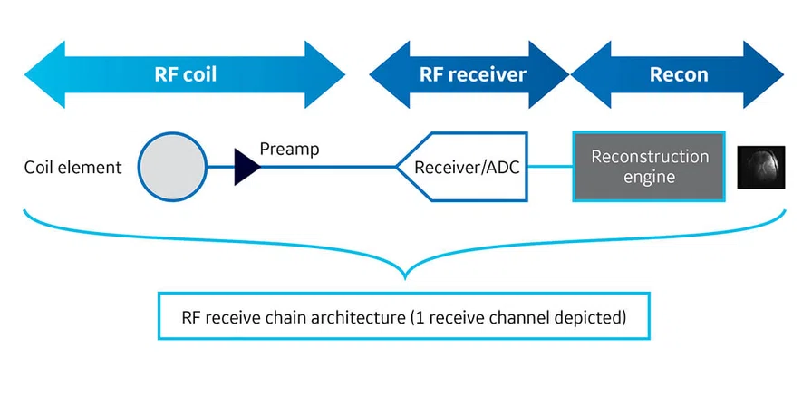
Figure 1.
RF receive chain architecture.
A
Figure 4.
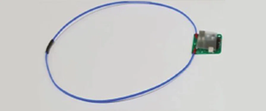
Conventional vs. AIR™ Coil loop. (A) Conventional design. (B) AIR™ Coil element loop design. (C) AIR™ Coil.
B
Figure 4.
Conventional vs. AIR™ Coil loop. (A) Conventional design. (B) AIR™ Coil element loop design. (C) AIR™ Coil.
1 Roemer PB, Edelstein WA, Hayes CE, Souza SP and Mueller OM 1990. The NMR Phased Array Magn Reson Med. 16 192-225.
2https://mriquestions.com/array-coils.html
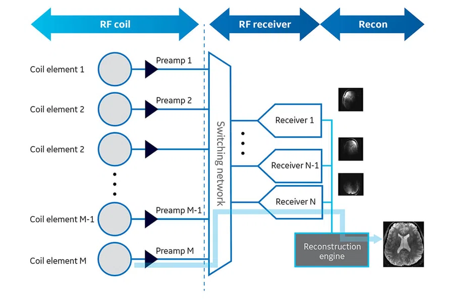
Figure 2.
M x N receive chain architecture.
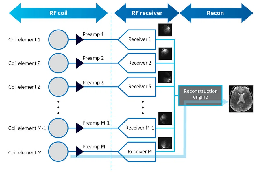
Figure 3.
M x M receive chain architecture.
Figure 6.
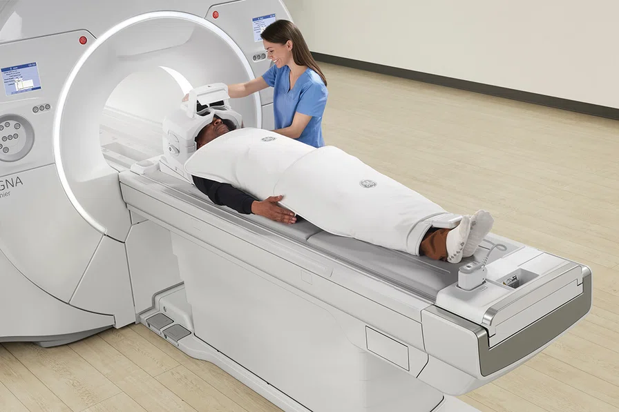
Patient setup with multiple overlapped AIR™ Coils.
Figure 6.
Patient setup with multiple overlapped AIR™ Coils.
C
Figure 4.
Conventional vs. AIR™ Coil loop. (A) Conventional design. (B) AIR™ Coil element loop design. (C) AIR™ Coil.
3 McGee KP, Stormont RS, Lindsay SA, Taracila V, Savitski D, Robb F, Witte R, Kaufmann T, Huston J, Riederer RJ, Borisch E, Rossman P 2018. Characterization and evaluation of a flexible MRI receive coil array for radiation therapy MR treatment planning using highly decoupled RF circuits. Physics in Medicine and Biology. 63.
Figure 5.
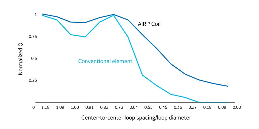
Conventional vs. AIR™ Coil overlapping capability.
Figure 7.
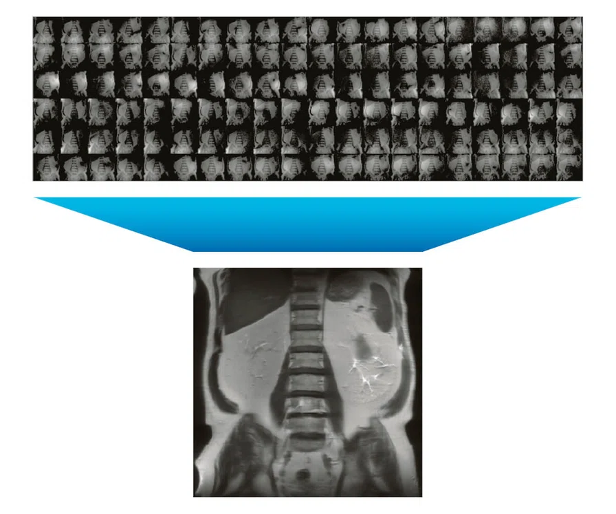
Sample 120 channel image generated with 120 RF elements and digitized simultaneously with 120 receivers/ADCs.
result


PREVIOUS
${prev-page}
NEXT
${next-page}
Subscribe Now
Manage Subscription
FOLLOW US
Contact Us • Cookie Preferences • Privacy Policy • California Privacy PolicyDo Not Sell or Share My Personal Information • Terms & Conditions • Security
© 2024 GE HealthCare. GE is a trademark of General Electric Company. Used under trademark license.
TECH TRENDS
Optimized RF coil and receive chain architecture that enables the use of higher RF channels
Optimized RF coil and receive chain architecture that enables the use of higher RF channels
Advancements in academic and clinical research, along with continued innovation by manufacturers, have steadily progressed MR imaging technology. Perhaps no other MR hardware subsystem has advanced as much as the radio frequency (RF) coils and receiver technology. Beginning with the invention of the phased array RF coil technology, MR systems image the anatomy with higher SNR and also cover large volumes with multiple coil elements to deliver excellent image quality1. Over the last two decades, a large number of accelerated imaging techniques have delivered improved image quality with decreased scan times. These accelerated imaging techniques provide the current impetus for the design of modern MR scanners capable of 128+ channel imaging. To achieve this level of modern system functionality and performance requires a careful orchestration of both RF coils and the RF receiver system design.
It is not surprising, given the rapid speed of technical development in this area, that there is a fair amount of confusion in the industry. This article discusses some basic definitions and design approaches used in the industry today. GE Healthcare SIGNA™ MR systems provide the ideal combination of receiver system and RF coil technology that results in the highest, industry-leading usable number of MR channels.
Number of RF coil elements connected simultaneously = M
M is the maximum number of coil elements connected simultaneously to the MR system. In everyday practice in the context of RF coils, people tend to use the terms ‘elements’ and ‘channels’ interchangeably. However, there are very important distinctions between these two terms. Failing to recognize the difference, notably when selecting an MR platform, could lead one to select a system that is less capable than assumed.
Number of RF receiver channels = analog-to-digital converters = N
An RF channel has a one-to-one relationship with the number (N) of analog to digital converters (ADC), also referred to as digital receivers. An ADC digitizes the analog signal received by a coil element that is used to contribute to the final image.
The MR receive chain architecture is comprised of multiple RF coil elements, preamplifiers, digitizers and a reconstruction computer (Figure 1). Each independent MR channel produces a partial image; these images are combined to form the composite image. To obtain an MR image of the area of interest in a single scan, the RF coil elements must contribute to the SNR and acceleration factor of the image2. It is important to understand that an MR channel cannot be established if one of the components, such as the digitizer or reconstruction computer, is missing.
Now, let’s examine the choices of architectures in the design of MR systems.
Conventional M x N MR receive chain designs
Most conventional MR systems utilize a limited receive chain design to minimize the cost of digital receivers/ADCs, which limits capability. By definition, the number of connected coil elements (M) is much larger than the number of elements that can be digitized at one time by a receiver/ADC (N). The signal from the coil elements (M) is routed to the receivers (N) with the use of a switching network (Figure 2). It is common for such systems to be identified as M x N receive systems, i.e., 204 x 48. Based on this architecture, the number of MR channels will be limited by the number of available receivers/ADCs, N. Continuing this example, where M = 204 and N = 48, regardless of how many coil elements are connected to the system, the number of MR channels cannot exceed 48. In this design, it is the number of receivers/ ADCs in the receive chain architecture that limits the number of MR channels.
These types of systems typically are sold with a set of limited RF coils that cannot push the limits of RF channels beyond that number. Therefore, in the example (M = 204 and N = 48), this MR system would not be able to utilize all elements of a 60-element torso RF coil without an upgrade.
While this type of conventional MR system design served the industry well for many years, it is not compatible with the emergence of coils with a higher number of elements and cannot enable the utilization of multiple connected coils simultaneously when the total element count exceeds the number of receivers (see section on AIR™ Coils).
Modern M x M receive chain design
In modern MR receive chain design, the shortcomings of a conventional design are avoided by significantly increasing the number of receivers/ADCs. In this system design, each independent coil element connected to the system is furnished with its own receiver/ADC (Figure 3). The number of simultaneously digitized elements is not limited and, therefore, can be equal to the number of connected coil elements (M). Any and all connected elements can be digitized simultaneously to form a full MR imaging channel. GE has pioneered this type of receive chain design with the introduction of Total Digital Imaging (TDI) on all newer generation MR systems.
The primary benefit of this system architecture is that it results in the largest possible number of MR channels for a given set of connected coils. It also allows for the adoption of new, higher element count RF coils as they are introduced into the clinical market. For example, a 146 channel SIGNA™ Premier system can connect and simultaneously digitize a maximum of 146 elements.
AIR™ Coils: Versatility with enhanced patient comfort
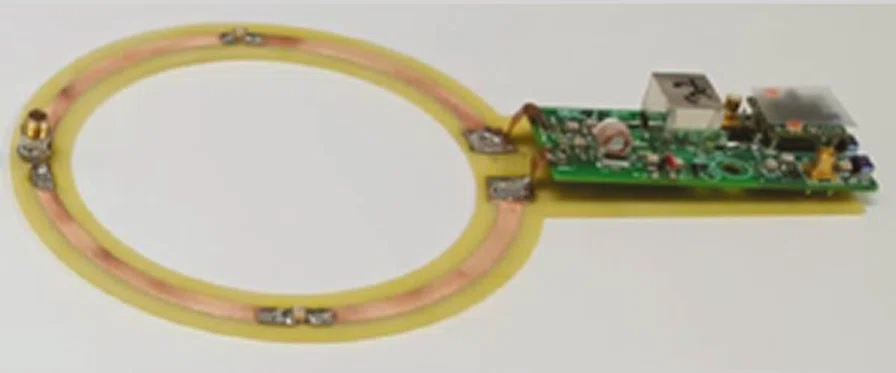
AIR™ Coils are extremely flexible and lightweight, leading the industry in these two areas. To achieve this evolution in coil design, the conventional rigid copper RF coil loop, bulky preamp and feedboard (Figure 4A) were replaced with a flexible lightweight wire loop and miniaturized RF electronics (Figure 4B).
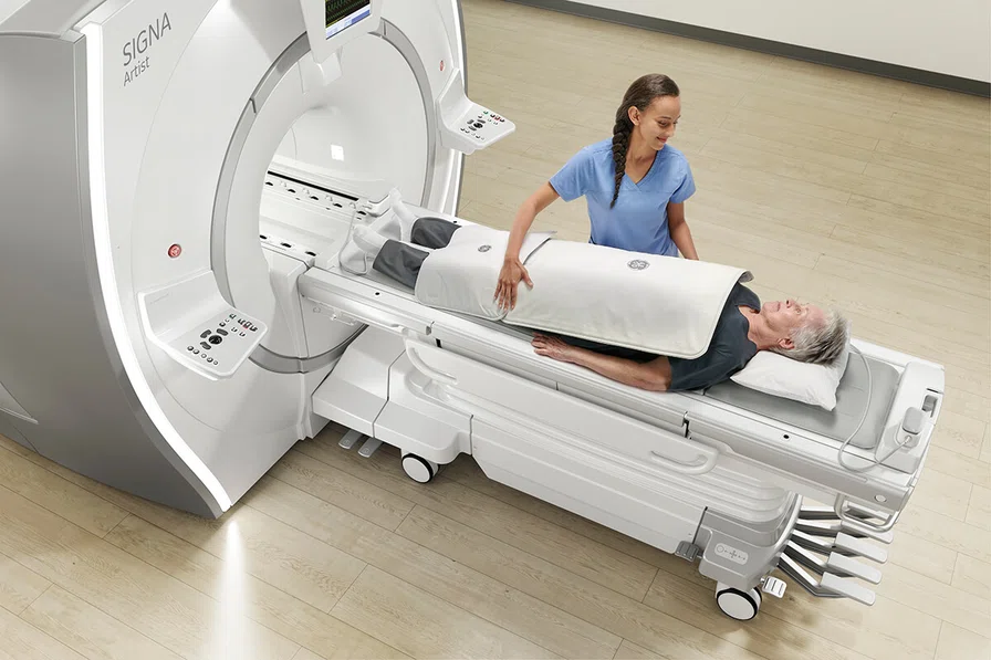
This innovative combination allows for an RF coil which looks and feels like a lightweight blanket (Figure 4C). Perhaps more importantly, the miniaturized AIR™ electronics allow for greater overlap between neighboring loops without the instabilities or signal destruction that would result with conventional RF coil designs. This allows for wrapping of the anatomy, for example a knee or an elbow, without loss of signal because the RF coil conforms very closely to the anatomy3. Figure 5 illustrates the Q factor, a measurement proportional to SNR, of two conventional RF elements in comparison to two AIR™ Coil elements as they are moved closer together and ultimately overlap. Conventional RF coil elements deliver the best SNR at the critical overlap; however, SNR degrades significantly when the loop overlap increases (Figure 5). AIR™ Coil elements are much less sensitive to the amount of overlap and significantly outperform conventional RF loops when the overlap is less than optimal.
This property allows AIR™ Coils to be used in conjunction with each other to combine for either larger coverage or higher coil density in clinical practice.
Figure 6 demonstrates patient setup using multiple AIR™ Coils that are overlapped and combined with the 60-element AIR™ Posterior Array Coil embedded in the table. Figure 7 takes this a step further and highlights AIR™’s unique immunity to overlapping elements within the FOV. For this demonstration, four AIR™ Coils, comprised of 120 individual coil elements, were combined with the TDI receiver architecture to independently digitize the signal from each coil element for reconstruction. The result is the final 120-channel abdominal image shown. In other words, Figure 7 demonstrates the use of 120 simultaneous RF receive channels within an imaging FOV.
It should be noted that the high channel count body image shown in Figure 7 was acquired and reconstructed on a commercially available GE MR system, without adding specialized hardware or software. This is due to the fact that AIR™ Coils and GE’s TDI receive chain architecture were designed to provide a flexible, yet simple and consistent approach for high channel count imaging in today’s clinical setting.
In conclusion, all recent GE SIGNA™ MR systems include the most advanced receive chain architecture, TDI, and provide true high channel-count performance. In many cases, the number of available receivers/ADCs well exceed today’s clinical RF element counts. This ensures the seamless introduction of higher element count RF coils and density per unit imaging volume with these systems, as they become available, without requiring any upgrades in hardware or software.


