1. Delin C, Silvera S, Djian P, et al. Treatment of conservative complete ruptures of the LCA: prospective study on the direct scarring of the LCA among patients pre-selected by the IRM in diffusion - Continuation of the study. Review of Orthopedic and Traumatological Surgery. 2011 Nov; 97 (7): S284.
A
Figure 1.
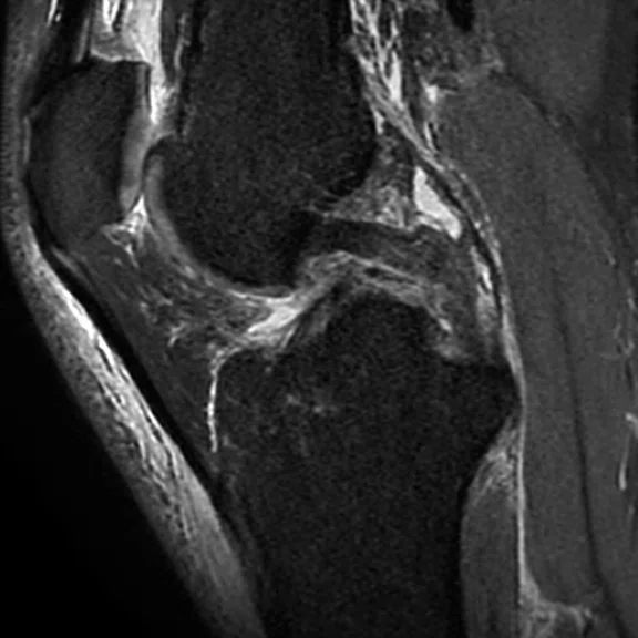
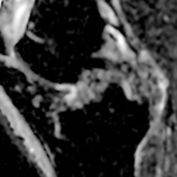
Patient with ACL tear clearly shown in two parts at the anteroinferior and posterosuperior areas, ACL (blue arrow) and PCL (yellow arrow). DWI and DTI are utilized to confirm that both segments of the torn ACL are in the same axis (arrows). (A, D) 3D Cube PD FatSat, (B) standard DWI b700 with (E) ADC map, (C) DTI 20 directions b400 and (F) FA map.
B
Figure 1.
Patient with ACL tear clearly shown in two parts at the anteroinferior and posterosuperior areas, ACL (blue arrow) and PCL (yellow arrow). DWI and DTI are utilized to confirm that both segments of the torn ACL are in the same axis (arrows). (A, D) 3D Cube PD FatSat, (B) standard DWI b700 with (E) ADC map, (C) DTI 20 directions b400 and (F) FA map.
C
Figure 1.
Patient with ACL tear clearly shown in two parts at the anteroinferior and posterosuperior areas, ACL (blue arrow) and PCL (yellow arrow). DWI and DTI are utilized to confirm that both segments of the torn ACL are in the same axis (arrows). (A, D) 3D Cube PD FatSat, (B) standard DWI b700 with (E) ADC map, (C) DTI 20 directions b400 and (F) FA map.
D
Figure 1.
Patient with ACL tear clearly shown in two parts at the anteroinferior and posterosuperior areas, ACL (blue arrow) and PCL (yellow arrow). DWI and DTI are utilized to confirm that both segments of the torn ACL are in the same axis (arrows). (A, D) 3D Cube PD FatSat, (B) standard DWI b700 with (E) ADC map, (C) DTI 20 directions b400 and (F) FA map.
E
Figure 1.
Patient with ACL tear clearly shown in two parts at the anteroinferior and posterosuperior areas, ACL (blue arrow) and PCL (yellow arrow). DWI and DTI are utilized to confirm that both segments of the torn ACL are in the same axis (arrows). (A, D) 3D Cube PD FatSat, (B) standard DWI b700 with (E) ADC map, (C) DTI 20 directions b400 and (F) FA map.
F
Figure 1.
Patient with ACL tear clearly shown in two parts at the anteroinferior and posterosuperior areas, ACL (blue arrow) and PCL (yellow arrow). DWI and DTI are utilized to confirm that both segments of the torn ACL are in the same axis (arrows). (A, D) 3D Cube PD FatSat, (B) standard DWI b700 with (E) ADC map, (C) DTI 20 directions b400 and (F) FA map.
A
Figure 2.
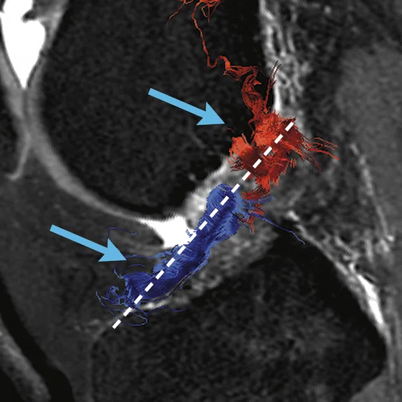
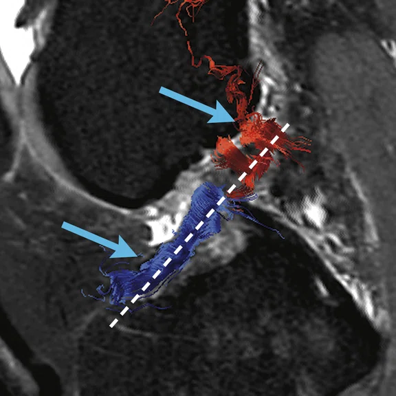
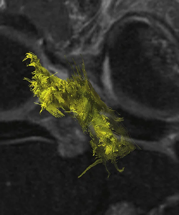
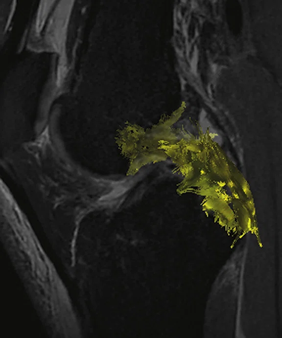
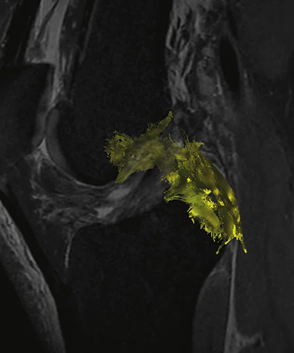
Same patient as Figure 1. (A-D) READYView FiberTracking clearly depicts the ACL tear (blue arrow) and PCL (yellow arrow). DWI and DTI are used to depict that the remnant fibers are well aligned in the native axis ligament. The rupture diagnosis is performed with 3D Cube.
B
Figure 2.
Same patient as Figure 1. (A-D) READYView FiberTracking clearly depicts the ACL tear (blue arrow) and PCL (yellow arrow). DWI and DTI are used to depict that the remnant fibers are well aligned in the native axis ligament. The rupture diagnosis is performed with 3D Cube.
C
Figure 2.
Same patient as Figure 1. (A-D) READYView FiberTracking clearly depicts the ACL tear (blue arrow) and PCL (yellow arrow). DWI and DTI are used to depict that the remnant fibers are well aligned in the native axis ligament. The rupture diagnosis is performed with 3D Cube.
D
Figure 2.
Same patient as Figure 1. (A-D) READYView FiberTracking clearly depicts the ACL tear (blue arrow) and PCL (yellow arrow). DWI and DTI are used to depict that the remnant fibers are well aligned in the native axis ligament. The rupture diagnosis is performed with 3D Cube.
A
Figure 3.
Case 2. (A-C) 3D Cube PD FatSat and (D) ADC map.
B
Figure 3.
Case 2. (A-C) 3D Cube PD FatSat and (D) ADC map.
C
Figure 3.
Case 2. (A-C) 3D Cube PD FatSat and (D) ADC map.
D
Figure 3.
Case 2. (A-C) 3D Cube PD FatSat and (D) ADC map.
A
Figure 4.
Example of this same technique on a PCL tear with (A-C) READYView FiberTracking reconstruction. DWI and DTI are used to depict that the remnant fibers are well aligned in the native axis ligament. The rupture diagnosis is performed with 3D Cube.
B
Figure 4.
Example of this same technique on a PCL tear with (A-C) READYView FiberTracking reconstruction. DWI and DTI are used to depict that the remnant fibers are well aligned in the native axis ligament. The rupture diagnosis is performed with 3D Cube.
C
Figure 4.
Example of this same technique on a PCL tear with (A-C) READYView FiberTracking reconstruction. DWI and DTI are used to depict that the remnant fibers are well aligned in the native axis ligament. The rupture diagnosis is performed with 3D Cube.
result


PREVIOUS
${prev-page}
NEXT
${next-page}
Subscribe Now
Manage Subscription
FOLLOW US
Contact Us • Cookie Preferences • Privacy Policy • California Privacy PolicyDo Not Sell or Share My Personal Information • Terms & Conditions • Security
© 2024 GE HealthCare. GE is a trademark of General Electric Company. Used under trademark license.
CASE STUDIES
The role of DWI and DTI in conservative ACL rupture treatment
The role of DWI and DTI in conservative ACL rupture treatment
by Renaud Barthelemy, MD, radiologist, Clinique du Mail, Grenoble, France
In anterior cruciate ligament (ACL) rupture, the gold standard in treatment management is primarily surgery, mainly autographs. Two alternative methods have emerged: ACL repair and spontaneous healing with a dedicated brace known as the Delin protocol1. For these two techniques, MR is the cornerstone for identifying appropriate patients for these protocols.
For patients selected for surgery, early rehabilitation is preferred to avoid quadriceps atrophy and stiffness. For spontaneous healing (Delin protocol) patients, immobilization of the knee with a brace is prescribed for 12 weeks. Ideally, the brace is placed as soon as possible after the initial trauma.
Case 1
Patient history
A 45-year-old male suffered right knee trauma from a skiing accident, including flexion and external rotation. The rescue team placed a dedicated brace on the patient’s leg immediately. The ski resort’s general practitioner suspected a complete ACL tear and the patient received an MR exam 12 days later.
Results
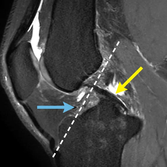
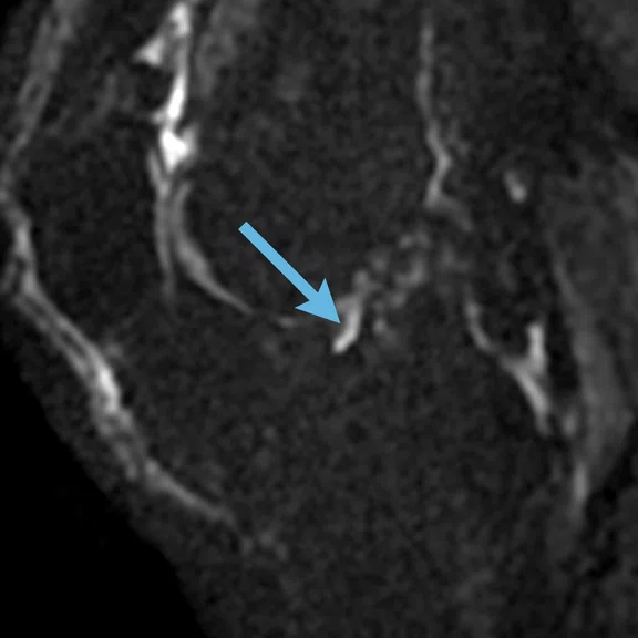
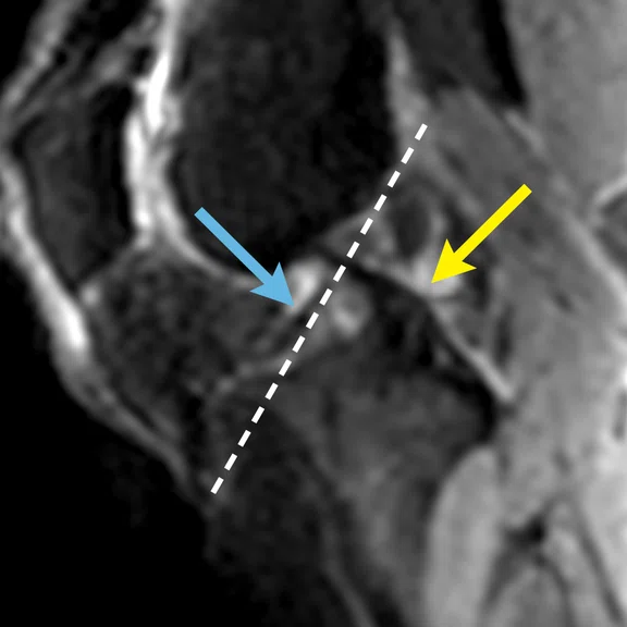
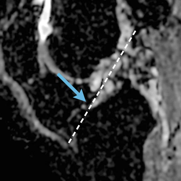
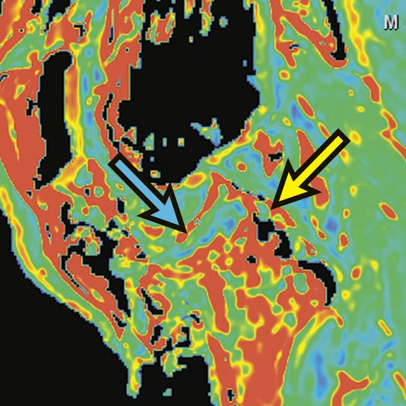
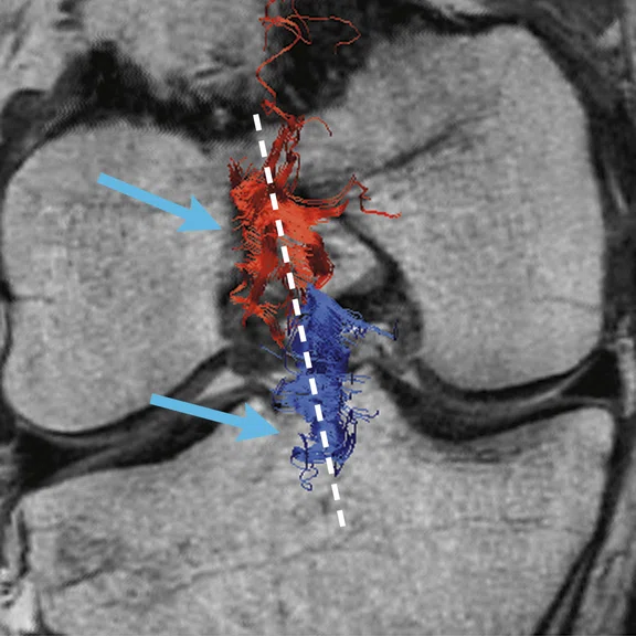
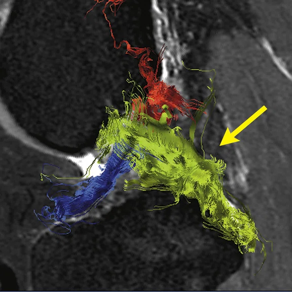
On 3D Cube images, the ACL tear is clearly shown in two parts: anteroinferior part and posterosuperior part. DTI is compared to standard DWI to confirm that both two parts of ACL are in the same axis. Using READYView FiberTracking helps depict the ACL tear.
Figure 1.
Patient with ACL tear clearly shown in two parts at the anteroinferior and posterosuperior areas, ACL (blue arrow) and PCL (yellow arrow). DWI and DTI are utilized to confirm that both segments of the torn ACL are in the same axis (arrows). (A, D) 3D Cube PD FatSat, (B) standard DWI b700 with (E) ADC map, (C) DTI 20 directions b400 and (F) FA map.
Case 2
Patient history
A 46-year-old male fell off a bicycle with his knee flexed at 90 degrees, incurring direct trauma on the anterior tibial tuberosity with reduced anteriorposterior laxity. MR performed eight days after injury.
Results
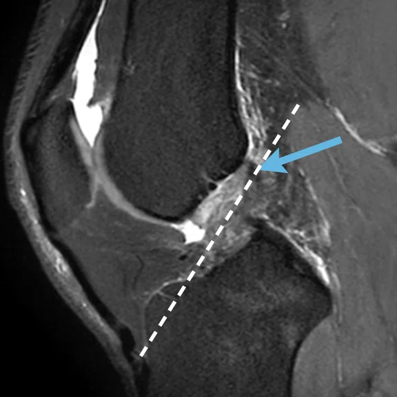
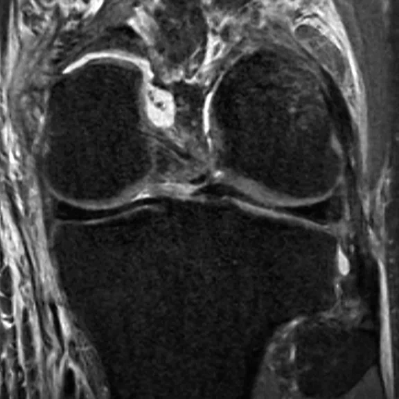
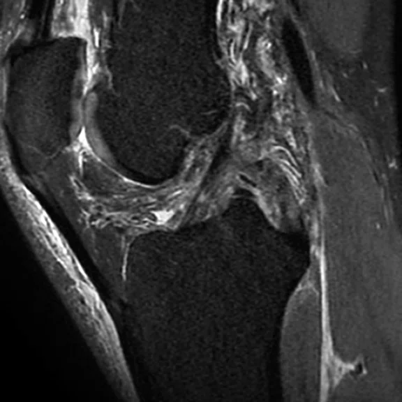
Example of this same technique on a PCL tear. With READYView FiberTracking reconstruction, it is possible to visualize the PCL tear.
Discussion
Since these two protocols have opposite treatment pathways, it is critical to perform the MR exam as soon as possible – no later than one week after trauma – and determine the potential for spontaneous healing. MR is the best imaging tool to visualize whether the remnant fibers have stayed in position along the native ACL axis after the rupture. Remnant fibers must be aligned along the Blumensaat line (also referred to as the intercondylar line). If there is any retraction or migration (e.g., horizontalization) then the use of spontaneous healing is not possible. Since 2008, we have added diffusion-weighted imaging (DWI) to the conventional MR protocols (T1, T2 FatSat or PD FatSat, 3D/isotropic) to remove signal from edema and hemorrhage to visualize the orientation of remnant fibers. We are now evaluating DTI with the ADC map and FiberTrack to determine if it can improve the interpretation of remnant fiber alignment and whether the sequence and associated post-processing can replace the conventional DWI with ADC map. We also anticipate that better illustration of remnant fibers, and the ability to track fibers in all orientations using FiberTracking, will assist the surgeon in cases referred for the surgical ACL repair technique.
The Delin protocol for ACL and PCL rupture
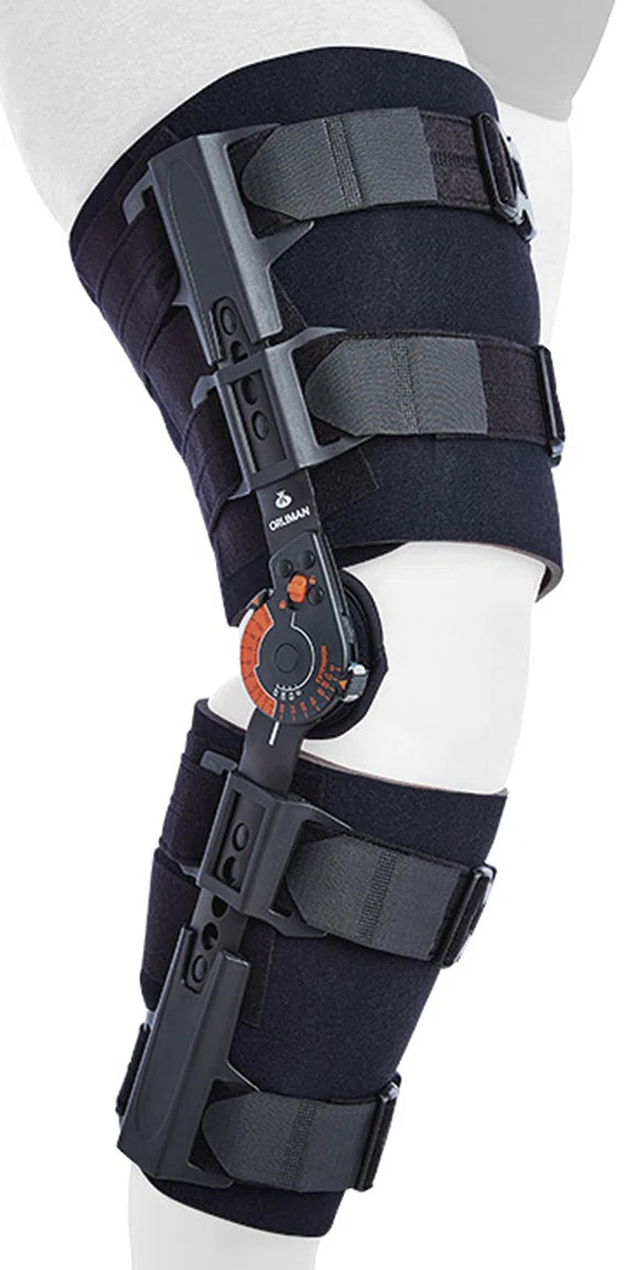
The Delin protocol is a conservative treatment for knee ACL rupture without surgery. The ACL is protected during the healing period with a brace that limits range of motion, avoiding maximum flexion and extension. This brace is worn 24/7 for 12 weeks without other treatment or rehabilitation. In the first six weeks, the leg is positioned at a 30/60 degree angle with the heel elevated off the ground (see photo). Another MR exam is performed at six weeks to identify non-healing cases (referred for surgery), followed by a progressive increase in the range of motion for the remaining six weeks. After the full 12-week immobilization period, the knee will be stiff and amyotrophy of the quadriceps can be quite extensive. Therefore, it is very important to select only patients with a very good chance to heal using this protocol. After 12 weeks the patient begins rehabilitation.
This protocol was first described at the 2008 French Orthopedic Society for ACL rupture by Cyrille Delin, MD, a radiologist specializing in osteo-articular imaging.


