Figure 6.
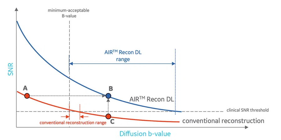
SNR as a function of applied diffusion b-value. The SNR of both conventional and AIR™ Recon DL varies as an exponential decay. AIR™ Recon DL allows higher b-values while maintaining sufficient clinical SNR.
A
Figure 9.
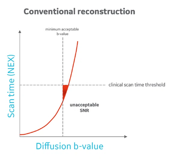
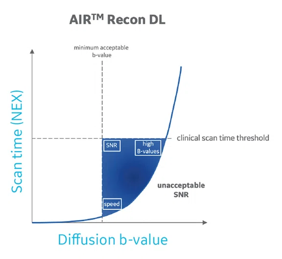
Expanded protocol space with AIR™ Recon DL. Protocol space is defined as those protocols that provide sufficiently high SNR, but simultaneously have acceptably low scan time and acceptably high b-value for diffusion-weighted contrast. Shown are protocol spaces for (A) conventional in the triangular red area and (B) AIR™ Recon DL in the blue area. The protocol space for AIR™ Recon DL (blue area) represents more protocol combinations of b-value and scan times that are clinically acceptable.
B
Figure 9.
Expanded protocol space with AIR™ Recon DL. Protocol space is defined as those protocols that provide sufficiently high SNR, but simultaneously have acceptably low scan time and acceptably high b-value for diffusion-weighted contrast. Shown are protocol spaces for (A) conventional in the triangular red area and (B) AIR™ Recon DL in the blue area. The protocol space for AIR™ Recon DL (blue area) represents more protocol combinations of b-value and scan times that are clinically acceptable.
A
Figure 10.
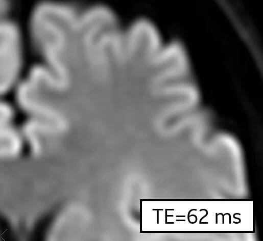
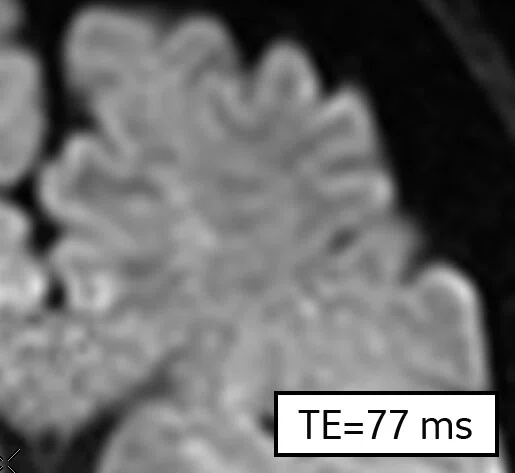
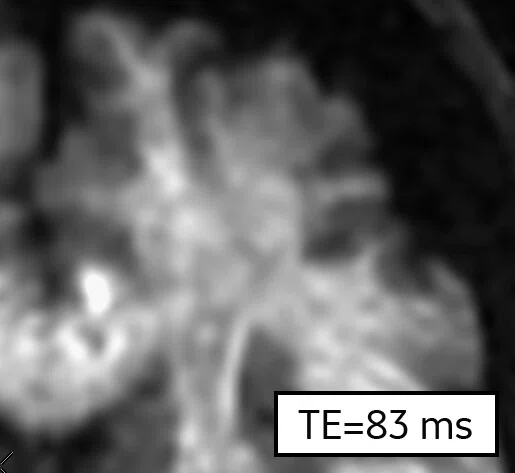
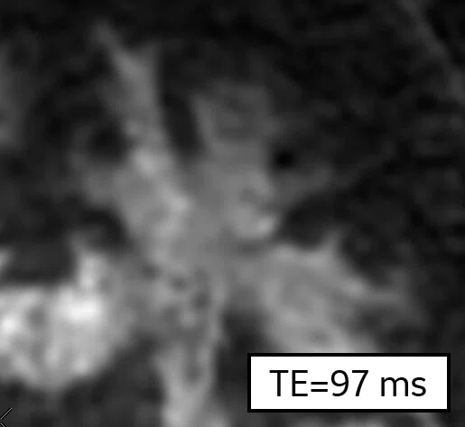
The impact of AIR™ Recon DL and advanced gradients on DWI SNR. Shown are 10 NEX images with a 1.5 x 1.5 x 3 mm resolution and b-values of 1000, 2500, 5000 and 10000 s/mm2 using (A) conventional reconstruction, (B) AIR™ Recon DL and (C) AIR™ Recon DL with reduced TEs from advanced gradient configuration. (C) Note the reduced TE settings and higher SNR. (A) and (B) were reconstructed from the same raw data.
B
Figure 10.
The impact of AIR™ Recon DL and advanced gradients on DWI SNR. Shown are 10 NEX images with a 1.5 x 1.5 x 3 mm resolution and b-values of 1000, 2500, 5000 and 10000 s/mm2 using (A) conventional reconstruction, (B) AIR™ Recon DL and (C) AIR™ Recon DL with reduced TEs from advanced gradient configuration. (C) Note the reduced TE settings and higher SNR. (A) and (B) were reconstructed from the same raw data.
C
Figure 10.
The impact of AIR™ Recon DL and advanced gradients on DWI SNR. Shown are 10 NEX images with a 1.5 x 1.5 x 3 mm resolution and b-values of 1000, 2500, 5000 and 10000 s/mm2 using (A) conventional reconstruction, (B) AIR™ Recon DL and (C) AIR™ Recon DL with reduced TEs from advanced gradient configuration. (C) Note the reduced TE settings and higher SNR. (A) and (B) were reconstructed from the same raw data.
1. The clinical benefits of AIR™ Recon DL for MR image reconstruction. September 2020. https://www.gehealthcare.com/-/jssmedia/c943df5927a049bb9ac95a9f0349ad8c.pdf.
2. Lebel, R.M. Performance characterization of a novel deep learning-based MR image reconstruction pipeline. August 2020. https://arxiv.org/abs/2008.06559.
1. The clinical benefits of AIR™ Recon DL for MR image reconstruction. September 2020. https://www.gehealthcare.com/-/jssmedia/c943df5927a049bb9ac95a9f0349ad8c.pdf.
3. Kim M, Kim HS, Kim HJ, et al. Thin-Slice Pituitary MRI with Deep Learning-based Reconstruction: Diagnostic Performance in a Postoperative Setting. Radiology. 2021 Jan;298(1):114- 122. Asan Medical Center, Seoul, Korea.
4. Van der Velde N, Hassing HC, Bakker BJ, et al. Improvement of late gadolinium enhancement image quality using a deep learning-based reconstruction algorithm and its influence on myocardial scar quantification. Eur Radiol. 2020 Nov 21. Erasmus Medical Center, Rotterdam, The Netherlands.
5. Wang X, Ma J, Bhosale P, et al. Novel deep learning-based noise reduction technique for prostate magnetic resonance imaging. Abdom Radiol (NY). 2021 Feb 12. The University of Texas MD Anderson Cancer Center, Houston, TX.
Figure 3.
SNR as a function of scan time (NEX). The SNR of both conventional and AIR™ Recon DL varies as the square root of scan time. AIR™ Recon DL allows reduced scan times while maintaining sufficient clinical SNR.
Figure 4.
Representative brain images to correspond to points (A-C) in Figure 3. Shown are b=2500 s/mm2 images with a 1.5 x 1.5 x 3 mm resolution, using (A) conventional reconstruction with 5 NEX, (B) AIR™ Recon DL with 1 NEX, and (C) conventional reconstruction with 1 NEX. In this example, (A) has sufficient SNR, but is considered too long a scan time. (B) AIR™ Recon DL delivers high SNR with clinically acceptable scan time. (B) and (C) were reconstructed from the same raw data.
B
Figure 4.
Representative brain images to correspond to points (A-C) in Figure 3. Shown are b=2500 s/mm2 images with a 1.5 x 1.5 x 3 mm resolution, using (A) conventional reconstruction with 5 NEX, (B) AIR™ Recon DL with 1 NEX, and (C) conventional reconstruction with 1 NEX. In this example, (A) has sufficient SNR, but is considered too long a scan time. (B) AIR™ Recon DL delivers high SNR with clinically acceptable scan time. (B) and (C) were reconstructed from the same raw data.
C
Figure 4.
Representative brain images to correspond to points (A-C) in Figure 3. Shown are b=2500 s/mm2 images with a 1.5 x 1.5 x 3 mm resolution, using (A) conventional reconstruction with 5 NEX, (B) AIR™ Recon DL with 1 NEX, and (C) conventional reconstruction with 1 NEX. In this example, (A) has sufficient SNR, but is considered too long a scan time. (B) AIR™ Recon DL delivers high SNR with clinically acceptable scan time. (B) and (C) were reconstructed from the same raw data.
Figure 8.
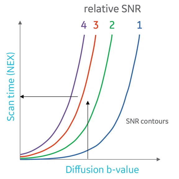
SNR contours for scan time and applied diffusion b-value. Shown are four SNR contours, generated with an exponential decay and square root dependence on b-value and scan time, respectively. The black horizontal arrow demonstrates the exponential decay relationship of SNR with b-value, if scan time is held constant. The black vertical arrow demonstrates the square root relationship of SNR with scan time, if b-value is held constant.
A
Figure 7.
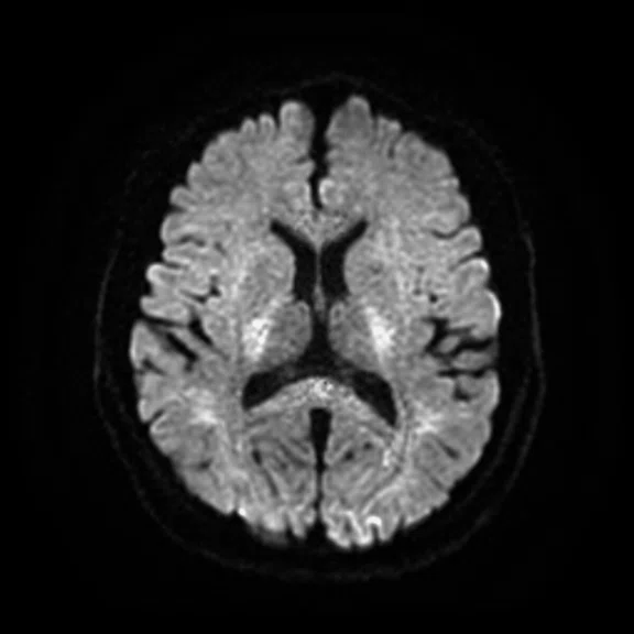
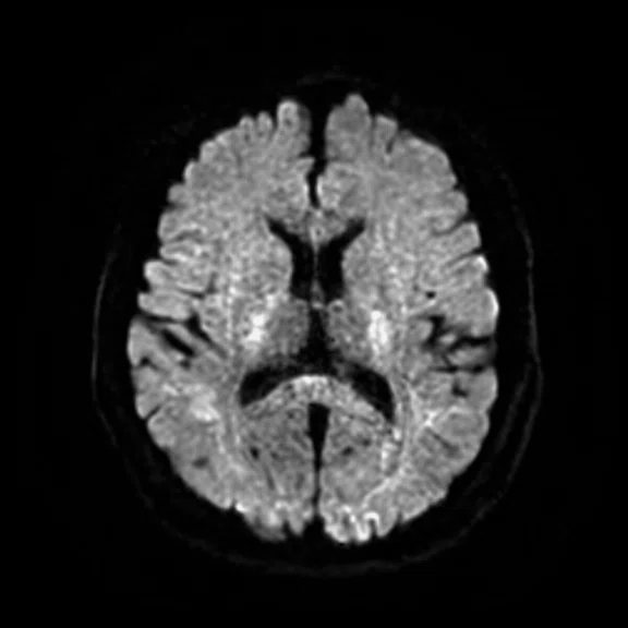
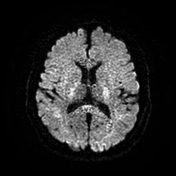
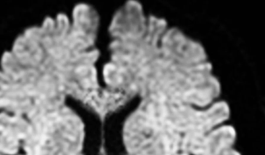
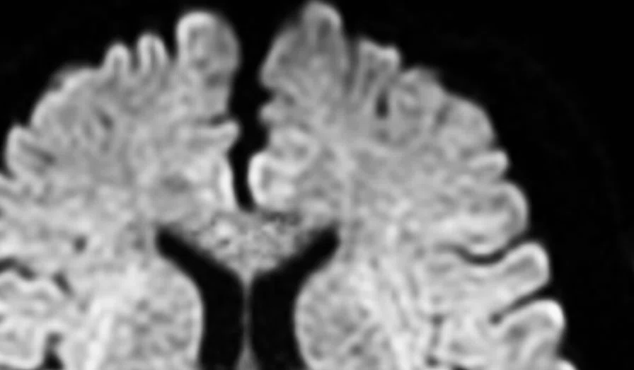
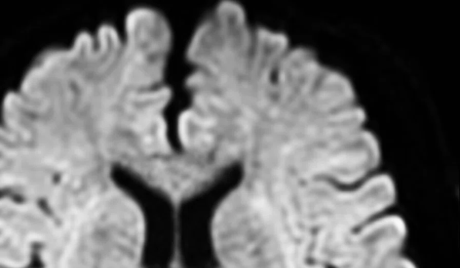
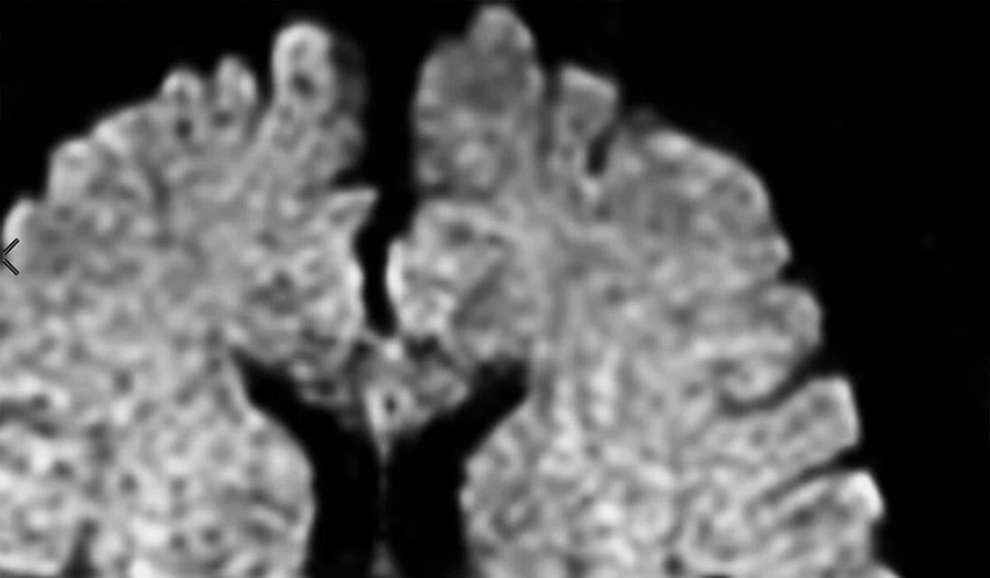
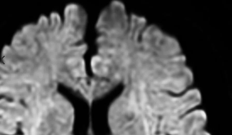
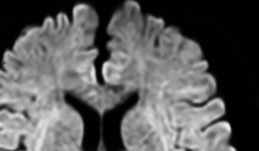
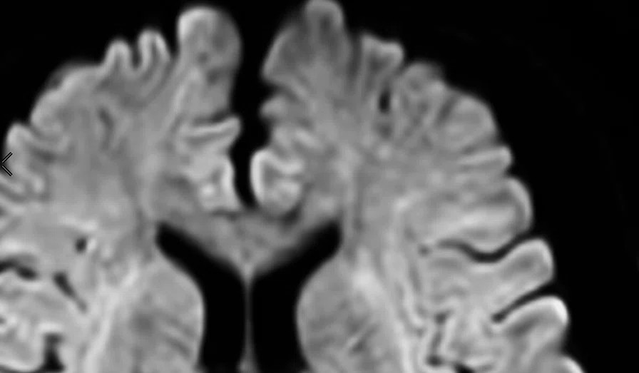
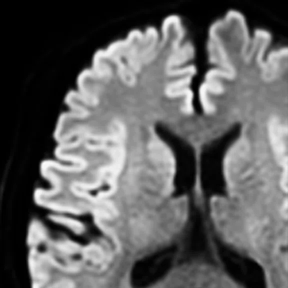
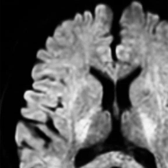
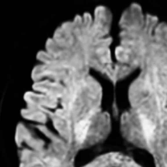
Representative brain images to correspond to points A, B and C in Figure 6. Shown are 5 NEX images with a 1.5 x 1.5 x 3 mm resolution, using (A) conventional reconstruction with b = 1000 s/mm2 (B) AIR™ Recon DL with b = 2500 s/mm2, and (C) conventional with b = 2500 s/ mm2. In this example, (A) has sufficient SNR, but lacks diffusion-weighted contrast, as evidenced by the high gray matter signal while (C) has acceptable diffusion-weighted contrast, but lacks SNR. (B) AIR™ Recon DL delivers high SNR with clinically acceptable contrast. (B) and (C) were reconstructed from the same raw data.
B
Figure 7.
Representative brain images to correspond to points A, B and C in Figure 6. Shown are 5 NEX images with a 1.5 x 1.5 x 3 mm resolution, using (A) conventional reconstruction with b = 1000 s/mm2 (B) AIR™ Recon DL with b = 2500 s/mm2, and (C) conventional with b = 2500 s/ mm2. In this example, (A) has sufficient SNR, but lacks diffusion-weighted contrast, as evidenced by the high gray matter signal while (C) has acceptable diffusion-weighted contrast, but lacks SNR. (B) AIR™ Recon DL delivers high SNR with clinically acceptable contrast. (B) and (C) were reconstructed from the same raw data.
C
Figure 7.
Representative brain images to correspond to points A, B and C in Figure 6. Shown are 5 NEX images with a 1.5 x 1.5 x 3 mm resolution, using (A) conventional reconstruction with b = 1000 s/mm2 (B) AIR™ Recon DL with b = 2500 s/mm2, and (C) conventional with b = 2500 s/ mm2. In this example, (A) has sufficient SNR, but lacks diffusion-weighted contrast, as evidenced by the high gray matter signal while (C) has acceptable diffusion-weighted contrast, but lacks SNR. (B) AIR™ Recon DL delivers high SNR with clinically acceptable contrast. (B) and (C) were reconstructed from the same raw data.
A
Figure 2.
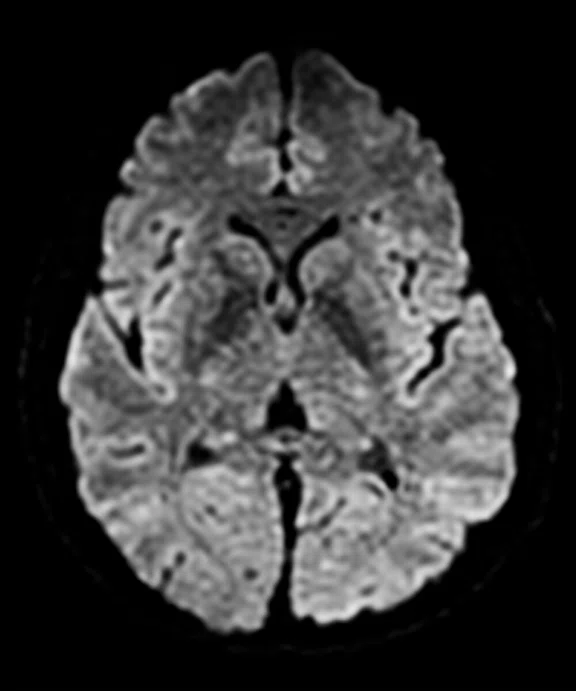
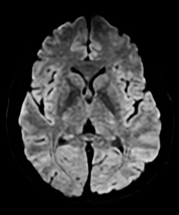
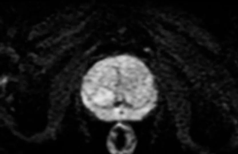
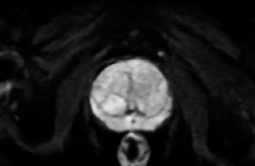
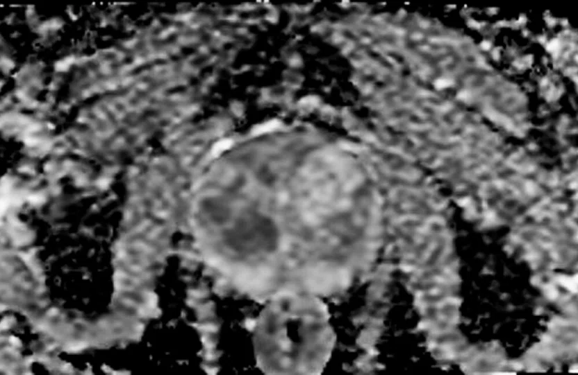
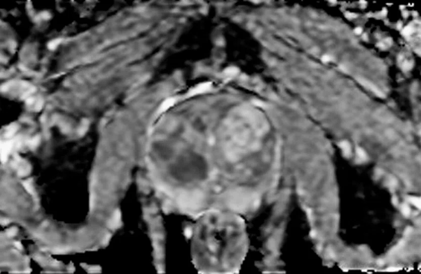
Representative diffusion-weighted images in the brain, spine and prostate without and with AIR™ Recon DL. (A-C) The same image is shown with both conventional and AIR™ Recon DL reconstructions with the high setting of the same raw data. (D) Apparent diffusion coefficient (ADC) maps are shown for the prostate.
B
Figure 2.
Representative diffusion-weighted images in the brain, spine and prostate without and with AIR™ Recon DL. (A-C) The same image is shown with both conventional and AIR™ Recon DL reconstructions with the high setting of the same raw data. (D) Apparent diffusion coefficient (ADC) maps are shown for the prostate.
C
Figure 2.
Representative diffusion-weighted images in the brain, spine and prostate without and with AIR™ Recon DL. (A-C) The same image is shown with both conventional and AIR™ Recon DL reconstructions with the high setting of the same raw data. (D) Apparent diffusion coefficient (ADC) maps are shown for the prostate.
D
Figure 2.
Representative diffusion-weighted images in the brain, spine and prostate without and with AIR™ Recon DL. (A-C) The same image is shown with both conventional and AIR™ Recon DL reconstructions with the high setting of the same raw data. (D) Apparent diffusion coefficient (ADC) maps are shown for the prostate.
E
Figure 5.
AIR™ Recon DL delivers more SNR with fewer NEX. Shown are b=2500 s/mm2 images with (A-D) conventional and (E-H) AIR™ Recon DL reconstructions. For each NEX setting, the same raw data was used for both reconstructions. Visual comparison shows equivalent SNR between (E) and (B), and between (F) and (D).
F
Figure 5.
AIR™ Recon DL delivers more SNR with fewer NEX. Shown are b=2500 s/mm2 images with (A-D) conventional and (E-H) AIR™ Recon DL reconstructions. For each NEX setting, the same raw data was used for both reconstructions. Visual comparison shows equivalent SNR between (E) and (B), and between (F) and (D).
G
Figure 5.
AIR™ Recon DL delivers more SNR with fewer NEX. Shown are b=2500 s/mm2 images with (A-D) conventional and (E-H) AIR™ Recon DL reconstructions. For each NEX setting, the same raw data was used for both reconstructions. Visual comparison shows equivalent SNR between (E) and (B), and between (F) and (D).
H
Figure 5.
AIR™ Recon DL delivers more SNR with fewer NEX. Shown are b=2500 s/mm2 images with (A-D) conventional and (E-H) AIR™ Recon DL reconstructions. For each NEX setting, the same raw data was used for both reconstructions. Visual comparison shows equivalent SNR between (E) and (B), and between (F) and (D).
Figure 1.
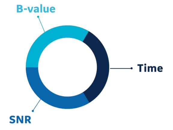
Conventional diffusion-weighted imaging is historically a balancing act between SNR, diffusion-weighting, b-value and scan time.
result
A
Figure 5.
AIR™ Recon DL delivers more SNR with fewer NEX. Shown are b=2500 s/mm2 images with (A-D) conventional and (E-H) AIR™ Recon DL reconstructions. For each NEX setting, the same raw data was used for both reconstructions. Visual comparison shows equivalent SNR between (E) and (B), and between (F) and (D).
B
Figure 5.
AIR™ Recon DL delivers more SNR with fewer NEX. Shown are b=2500 s/mm2 images with (A-D) conventional and (E-H) AIR™ Recon DL reconstructions. For each NEX setting, the same raw data was used for both reconstructions. Visual comparison shows equivalent SNR between (E) and (B), and between (F) and (D).
C
Figure 5.
AIR™ Recon DL delivers more SNR with fewer NEX. Shown are b=2500 s/mm2 images with (A-D) conventional and (E-H) AIR™ Recon DL reconstructions. For each NEX setting, the same raw data was used for both reconstructions. Visual comparison shows equivalent SNR between (E) and (B), and between (F) and (D).
D
Figure 5.
AIR™ Recon DL delivers more SNR with fewer NEX. Shown are b=2500 s/mm2 images with (A-D) conventional and (E-H) AIR™ Recon DL reconstructions. For each NEX setting, the same raw data was used for both reconstructions. Visual comparison shows equivalent SNR between (E) and (B), and between (F) and (D).


PREVIOUS
${prev-page}
NEXT
${next-page}
Subscribe Now
Manage Subscription
FOLLOW US
Contact Us • Cookie Preferences • Privacy Policy • California Privacy PolicyDo Not Sell or Share My Personal Information • Terms & Conditions • Security
© 2024 GE HealthCare. GE is a trademark of General Electric Company. Used under trademark license.
TECH TRENDS
AIR Recon DL for diffusion-weighted imaging
AIR Recon DL for diffusion-weighted imaging
by Robert D. Peters, PhD, Global MR Product Marketing Director, and Steve Lawson, RT(R)(MR), Global MR Clinical Marketing Manager, GE Healthcare
A groundbreaking innovation in MR
AIR™ Recon DL is a pioneering new deep-learning-based MR imaging reconstruction that challenges the historic trade-off in MR by delivering higher SNR and sharper images, while enabling shorter scan times. It has been heralded as one of the most significant innovations in MR technology in several decades.
AIR™ Recon DL is not a DICOM image filter. It improves image quality at the foundational level by making use of raw data to remove image noise and truncation or ringing artifacts.1,2 The user can set a preferred level of SNR improvement and the reconstructed images appear directly at the MR console on scan completion. AIR™ Recon DL is compatible with all anatomies.
The clinical benefits of AIR™ Recon DL have been extensively described and evaluated,1, 3-5 and it received regulatory clearance and was commercially released in 2020 for most 2D imaging sequences.
New capabilities
Most recently, AIR™ Recon DL for diffusion-weighted imaging (DWI) was made commercially available in 2021 through the SIGNA™Works AIR™ IQ Edition software release. In this article, we focus on the clinical benefits of AIR™ Recon DL with DWI, where SNR, b-value and scan time are often considered the primary competing factors (Figure 1).
Due to the flexibility of how the deep-learning based neural network was developed and trained, AIR™ Recon DL is compatible for all anatomies. Clinical users of AIR™ Recon DL for diffusion weighting have found it particularly useful in applications such as brain, spine and prostate (Figure 2).
B
Figure 2.
Representative diffusion-weighted images in the brain, spine and prostate without and with AIR™ Recon DL. (A-C) The same image is shown with both conventional and AIR™ Recon DL reconstructions with the high setting of the same raw data. (D) Apparent diffusion coefficient (ADC) maps are shown for the prostate.
Applications such as fast spin echo (FSE) require minor protocol modifications to make optimal use of AIR™ Recon DL, such as increasing readout bandwidth to reduce echo spacing, reduction in voxel volumes, reduction in number of averages or excitations (NEX) and increase in parallel imaging acceleration.3 With DWI, AIR™ Recon DL is often used without modification to the protocol parameters, with the exception of b-value and NEX. Prior to AIR™ Recon DL, DWI users had to carefully manage the SNR impact of too high a b-value and too low a NEX to achieve diagnostic performance. In the following sections, we will examine the impact of AIR™ Recon DL on SNR vs. scan time and SNR vs. b-value dependencies separately. Then we will examine how AIR™ Recon DL can lead to an expanded protocol space for diffusion-weighted imaging, leveraging the benefits of both scan time and b-value simultaneously.
SNR and scan time
The most common way to increase SNR is to acquire additional NEX. The unfortunate reality is that doubling the NEX only results in a square root of 2 improvement in the SNR. As scan time is directly proportional to NEX, we see that SNR varies only as the square root of scan time.
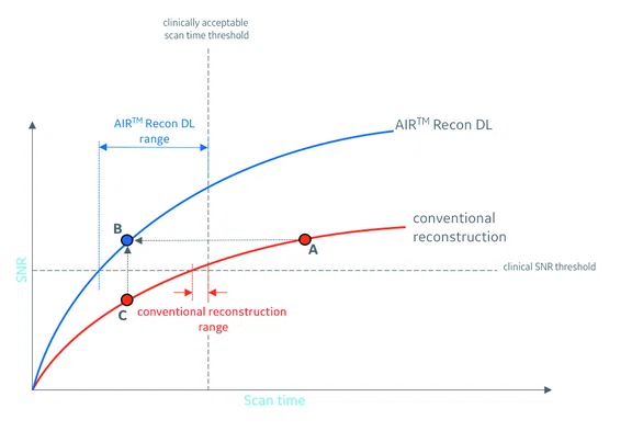
Consider Figure 3, showing this square root dependence of SNR on scan time (or NEX). If we were to model the SNR of AIR™ Recon DL images (blue curve) as being a simple multiplication of the conventional SNR (red curve), then we would see that both the AIR™ Recon DL and conventional reconstruction curves have a similar shape, with both plateauing with increasing scan times.
There will be clinical acceptance thresholds for SNR and scan time, as indicated by the horizontal and vertical dotted lines in Figure 3, respectively. These thresholds will generally be dependent on the imaging facility and reading radiologists. Basically, any protocol that leads to a specific SNR and scan time must fall above the SNR threshold and to the left of the scan time threshold.
If point A in Figure 3 represents a protocol using conventional reconstruction with an unacceptably long scan time (or NEX) but with sufficient SNR, then AIR™ Recon DL can deliver the same SNR in a significantly shorter scan time, as indicated by point B. Conversely, if a protocol using conventional reconstruction has clinically acceptable scan time but is lacking in SNR, such as in point C, then AIR™ Recon DL would improve the SNR to acceptance levels (point B).
With this perspective, it is also noteworthy that the scan time (or NEX) range is determined by where the SNR curve intercepts both the SNR and scan time thresholds. As such, AIR™ Recon DL has a considerably broader scan time range, as indicated in the horizontal double-sided blue arrow, compared to the conventional reconstruction range (red arrows). Representative images for points A, B and C are shown in Figure 4.
Figure 4.
Representative brain images to correspond to points (A-C) in Figure 3. Shown are b=2500 s/mm2 images with a 1.5 x 1.5 x 3 mm resolution, using (A) conventional reconstruction with 5 NEX, (B) AIR™ Recon DL with 1 NEX, and (C) conventional reconstruction with 1 NEX. In this example, (A) has sufficient SNR, but is considered too long a scan time. (B) AIR™ Recon DL delivers high SNR with clinically acceptable scan time. (B) and (C) were reconstructed from the same raw data.
In Figure 5, we see more closely how the SNR performance of AIR™ Recon DL compares to conventional reconstruction. The first observation is the decreasing improvement with NEX, showing almost no difference between 10 and 20 NEX for both conventional and AIR™ Recon DL reconstructions. Based on visual comparison, we see the AIR™ Recon DL image with 1 NEX (Figure 5E) compares with the conventional image with 5 NEX (Figure 5B). Similarly, we see comparable SNR between AIR™ Recon DL with 5 NEX (Figure 5F) and conventional with 20 NEX (Figure 5D).
1 NEX
(0:20)
5 NEX
(0:80)
10 NEX
(2:08)
20 NEX
(4:08)
Conventional
Comparable SNR
Comparable SNR

AIR™ Recon DL
Figure 5.
AIR™ Recon DL delivers more SNR with fewer NEX. Shown are b=2500 s/mm2 images with (A-D) conventional and (E-H) AIR™ Recon DL reconstructions. For each NEX setting, the same raw data was used for both reconstructions. Visual comparison shows equivalent SNR between (E) and (B), and between (F) and (D).
SNR and b-value
Diffusion weighting reveals important soft-tissue contrast and is achieved through the application of diffusion-weighted gradient pulses, which are quantified by their so-called b-value. Typically, the larger and longer the gradient pulses, the greater the b-value and the greater the diffusion weighting. However, the larger the b-value, the less the signal and SNR. The signal intensity follows an exponential decay model of S = So e-bD, where S is the observed signal, So is the signal in the absence of diffusion weighting and D is the apparent diffusion coefficient of the specific tissue. For gray and white matter, the diffusion coefficient is approximately 1 x 10⁻³ mm2/s and 0.7 x 10⁻³ mm2/s, respectively. This means the signal from gray matter will decay faster than white matter with increasing b-value. To put it into perspective, an applied b-value of 1000 s/mm2 will result in just 37% of the original signal of gray matter. With a b-value of 2500 s/mm2, this becomes only 8%.
The benefit of AIR™ Recon DL on diffusion-weighted SNR can be appreciated through Figure 6, which shows the exponential decay behavior of SNR with b-value. Similar to the previous discussion on SNR and scan time, the SNR of AIR™ Recon DL (blue curve) can be modelled as a multiplication of conventional reconstruction SNR (red curve), with both approaching zero with sufficiently high b-values. As before, clinical acceptance thresholds for SNR and b-value are represented by the horizontal and vertical dotted lines, respectively. As b-value determines diffusion-weighted contrast, imaging facilities will generally have a minimum-acceptable b-value. As such, any clinically acceptable protocol must deliver an SNR above the SNR threshold and use a b-value to the right of the acceptable b-value.
Point A in Figure 6 represents a protocol that uses conventional reconstruction with too low of a b-value, but delivers sufficient SNR. AIR™ Recon DL can deliver the same SNR but with a much higher b-value, as indicated by point B. Point C represents a protocol with conventional reconstruction that has an acceptably high b-value but lacks in SNR, which would be increased with the use of AIR™ Recon DL (point B). In Figure 6, we see how the useable clinical b-value range with AIR™ Recon DL (blue double-sided arrow) is considerably larger than that of conventional reconstruction (red arrows) due to the increased SNR. Representative images for points A, B and C are shown in Figure 7.
Figure 7.
Representative brain images to correspond to points A, B and C in Figure 6. Shown are 5 NEX images with a 1.5 x 1.5 x 3 mm resolution, using (A) conventional reconstruction with b = 1000 s/mm2 (B) AIR™ Recon DL with b = 2500 s/mm2, and (C) conventional with b = 2500 s/ mm2. In this example, (A) has sufficient SNR, but lacks diffusion-weighted contrast, as evidenced by the high gray matter signal while (C) has acceptable diffusion-weighted contrast, but lacks SNR. (B) AIR™ Recon DL delivers high SNR with clinically acceptable contrast. (B) and (C) were reconstructed from the same raw data.
Expanding the clinically usable DWI protocol space with AIR™ Recon DL
Now that we’ve examined the relationships between SNR with scan time and SNR with b-value separately, here we look at the more complete picture of protocol space and consider SNR, scan time and b-value all together.
First, we begin with describing the shape of SNR contours for scan time and b-values in Figure 8. Each curved contour line represents a constant SNR for different scan times and b-values. Four evenly spaced SNR levels are shown in blue, green, red and purple. Intuitively, we see that the SNR increases with increasing scan time, but decreases with increasing b-value.
Figure 8.
SNR contours for scan time and applied diffusion b-value. Shown are four SNR contours, generated with an exponential decay and square root dependence on b-value and scan time, respectively. The black horizontal arrow demonstrates the exponential decay relationship of SNR with b-value, if scan time is held constant. The black vertical arrow demonstrates the square root relationship of SNR with scan time, if b-value is held constant.
Clinically acceptable protocols are those that simultaneously meet three criteria: sufficiently high SNR, acceptably low scan time and acceptably high b-value. We can appreciate the size of this “protocol space” in Figure 9 for both conventional and AIR™ Recon DL reconstructions. In Figure 9A, we see that with conventional reconstruction, the narrow ranges on b-value and scan time lead to a small red triangular protocol space. This means that there are very limited protocol choices that meet clinical acceptance criteria with conventional reconstruction. Conversely, owing to the SNR performance, the protocol space of AIR™ Recon DL in Figure 9B is considerably larger, indicating there are far more protocol combinations available. In addition, with such a large protocol space, we see that it is possible to target AIR™ Recon DL’s use for speed, higher b-value or SNR. Most certainly, the larger protocol space with AIR™ Recon DL also helps avoid unexpected poor image quality when other protocol modifications are inadvertently made.
Figure 9.
Expanded protocol space with AIR™ Recon DL. Protocol space is defined as those protocols that provide sufficiently high SNR, but simultaneously have acceptably low scan time and acceptably high b-value for diffusion-weighted contrast. Shown are protocol spaces for (A) conventional in the triangular red area and (B) AIR™ Recon DL in the blue area. The protocol space for AIR™ Recon DL (blue area) represents more protocol combinations of b-value and scan times that are clinically acceptable.
AIR™ Recon DL and advanced gradient performance
We’ve seen that AIR™ Recon DL provides considerable clinical benefit over conventional reconstruction with balancing SNR, b-value and scan time in diffusion-weighted imaging. These benefits will lead to increased diffusion-weighted contrast through the use of higher b-values, faster scans, higher SNR and sharper images that are faster and easier to interpret.
Given the complexities of the MR system, it would be natural to question if advanced image reconstruction technologies such as AIR™ Recon DL could compensate for costly hardware subsystems, such as magnetic field strength, high-channel surface coils and even gradient performance. GE Healthcare believes that hardware-related components will continue to be important and clinically relevant simply because the higher the input SNR (as seen in the conventional reconstruction), the higher the output AIR™ Recon DL image SNR will be. In other words, the better the input, the better the output.
Let’s take gradient performance, for example, as this subsystem is particularly relevant to diffusion- weighted imaging. Advanced gradient technology can deliver higher peak amplitudes, higher slew rates and may employ gradient-waveform optimization, all of which translates to higher potential b-values and reduced minimum echo times (TE), thus delivering more diffusion-weighted contrast and higher SNR, respectively.
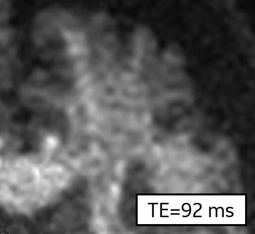
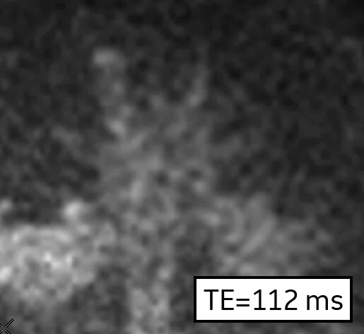
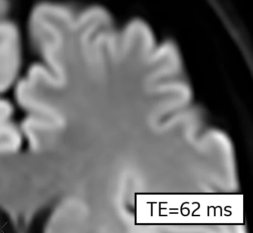
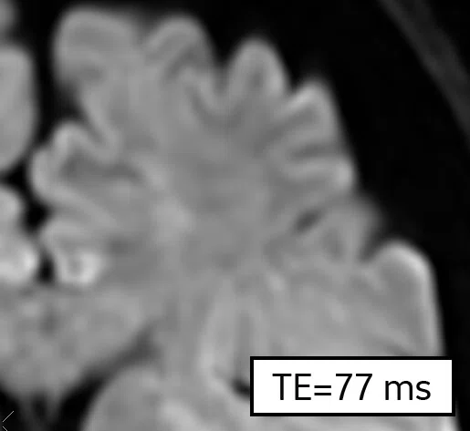
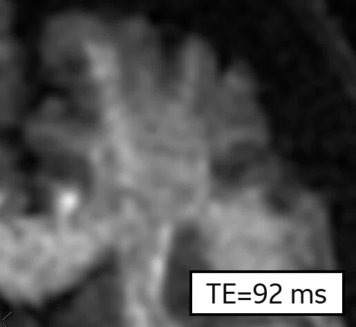
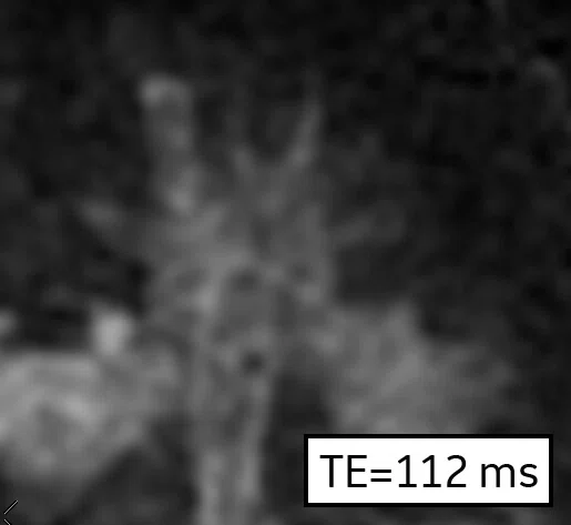
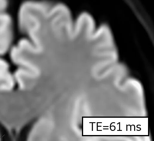
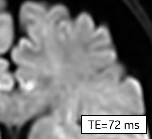
Consider Figure 10, which shows diffusion-weighted images with conventional and AIR™ Recon DL reconstructions of four different b-values, along with an advanced gradient configuration that leads to shorter TE settings. All images were obtained with 10 NEX to provide an abundance of starting SNR at the lowest b-value.
1000 s/mm2
2500 s/mm2
5000 s/mm2
10000 s/mm2
Figure 10.
The impact of AIR™ Recon DL and advanced gradients on DWI SNR. Shown are 10 NEX images with a 1.5 x 1.5 x 3 mm resolution and b-values of 1000, 2500, 5000 and 10000 s/mm2 using (A) conventional reconstruction, (B) AIR™ Recon DL and (C) AIR™ Recon DL with reduced TEs from advanced gradient configuration. (C) Note the reduced TE settings and higher SNR. (A) and (B) were reconstructed from the same raw data.
On the top row with conventional reconstruction, we see the impact of increasing b-value on SNR and how AIR™ Recon DL considerably improves the SNR (middle row), reconstructed from the same raw data. However, even more SNR is provided to the AIR™ Recon DL images with the use of an advanced gradient configuration that lead to reduced TE times. Notice how the b = 10000 images are borderline clinically acceptable with AIR™ Recon DL (middle row, TE of 112 ms), but are fully clinically acceptable with a reduced TE of 97 ms. One might suggest that the SNR benefit from the 15 ms shorter TE (middle row to bottom row) is almost comparable to the SNR gain from conventional to AIR™ Recon DL (top row to middle row).
Summary
For diffusion-weighted imaging, AIR™ Recon DL provides many clinical benefits over conventional reconstruction, including increased SNR, the ability to use higher b-values for greater diffusion-weighted contrast and shorter scan times.
With an understanding of the relationship between SNR, b-value and scan time, AIR™ Recon DL can significantly expand the clinically usable protocol space to allow users more freedom and flexibility in prescribing DWI scans to suit their particular needs. Although AIR™ Recon DL can deliver SNR improvement, hardware components that also deliver heightened SNR will remain relevant, such as advanced gradients.


