A
Figure 1.
STA-MCA bypass follow-up brain exam. After the upgrade, the slice thickness was changed from 1.2 mm to 0.9 mm for TOF MRA and from 5 mm to 4 mm for 2D axial acquisitions. (A) 3D TOF MRA with HyperSense, 0.7 x 0.9 x 0.9 mm, 5:34 min. (B) Axial DWI b1000 with AIR™ Recon DL, 1.4 x 1.4 x 4.0 mm, 1:28 min. (C) Axial FLAIR with AIR™ Recon DL, 0.6 x 0.8 x 4.0 mm, 3:21 min. (D) Axial T2* with AIR™ Recon DL, 0.6 x 0.6 x 4.0 mm, 1:58 min.
B
Figure 1.
STA-MCA bypass follow-up brain exam. After the upgrade, the slice thickness was changed from 1.2 mm to 0.9 mm for TOF MRA and from 5 mm to 4 mm for 2D axial acquisitions. (A) 3D TOF MRA with HyperSense, 0.7 x 0.9 x 0.9 mm, 5:34 min. (B) Axial DWI b1000 with AIR™ Recon DL, 1.4 x 1.4 x 4.0 mm, 1:28 min. (C) Axial FLAIR with AIR™ Recon DL, 0.6 x 0.8 x 4.0 mm, 3:21 min. (D) Axial T2* with AIR™ Recon DL, 0.6 x 0.6 x 4.0 mm, 1:58 min.
C
Figure 1.
STA-MCA bypass follow-up brain exam. After the upgrade, the slice thickness was changed from 1.2 mm to 0.9 mm for TOF MRA and from 5 mm to 4 mm for 2D axial acquisitions. (A) 3D TOF MRA with HyperSense, 0.7 x 0.9 x 0.9 mm, 5:34 min. (B) Axial DWI b1000 with AIR™ Recon DL, 1.4 x 1.4 x 4.0 mm, 1:28 min. (C) Axial FLAIR with AIR™ Recon DL, 0.6 x 0.8 x 4.0 mm, 3:21 min. (D) Axial T2* with AIR™ Recon DL, 0.6 x 0.6 x 4.0 mm, 1:58 min.
D
Figure 1.
STA-MCA bypass follow-up brain exam. After the upgrade, the slice thickness was changed from 1.2 mm to 0.9 mm for TOF MRA and from 5 mm to 4 mm for 2D axial acquisitions. (A) 3D TOF MRA with HyperSense, 0.7 x 0.9 x 0.9 mm, 5:34 min. (B) Axial DWI b1000 with AIR™ Recon DL, 1.4 x 1.4 x 4.0 mm, 1:28 min. (C) Axial FLAIR with AIR™ Recon DL, 0.6 x 0.8 x 4.0 mm, 3:21 min. (D) Axial T2* with AIR™ Recon DL, 0.6 x 0.6 x 4.0 mm, 1:58 min.
A
Figure 2.
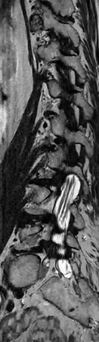
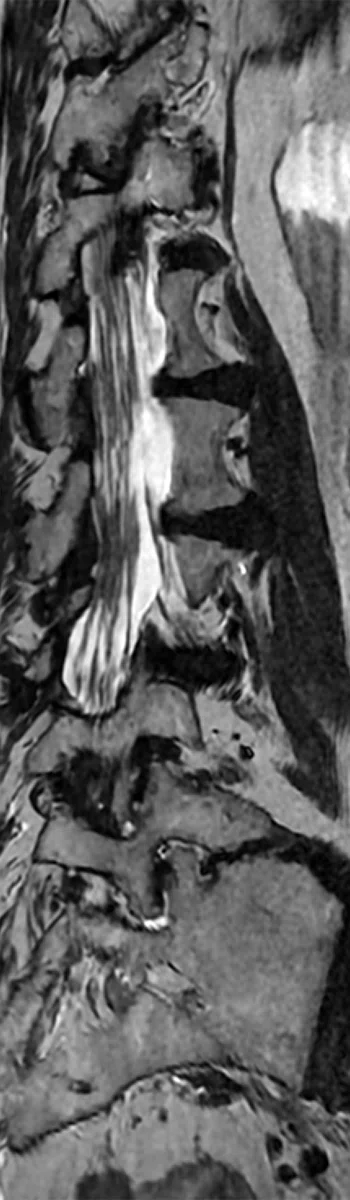
All images acquired with AIR™ Recon DL in the same patient with lumbar hernia using a (A) HNS CTL Coil and (B) integrated body coil. (A) Sagittal T2 FSE with AIR™ Recon DL and HNS CTL Coil, 0.7 x 0.9 x 3.0 mm, 1:23 min. (B) Sagittal T2 FSE with AIR™ Recon DL and integrated body coil (no surface coil used), 0.7 x 1.0 x 4.0 mm, 2:56 min.
B
Figure 2.
All images acquired with AIR™ Recon DL in the same patient with lumbar hernia using a (A) HNS CTL Coil and (B) integrated body coil. (A) Sagittal T2 FSE with AIR™ Recon DL and HNS CTL Coil, 0.7 x 0.9 x 3.0 mm, 1:23 min. (B) Sagittal T2 FSE with AIR™ Recon DL and integrated body coil (no surface coil used), 0.7 x 1.0 x 4.0 mm, 2:56 min.
A-1
Figure 3.
Comparison of wrist joint imaging in the same patient with Kienböck disease with (A) conventional protocol and (B) new protocol with AIR™ Recon DL. (A) Coronal STIR, 0.5 x 0.5 x 2.0 mm, 3:30 min. (B) Coronal STIR with AIR™ Recon DL, 0.3 x 0.4 x 2.0 mm, 1:52 min.
A-2
Figure 3.
Comparison of wrist joint imaging in the same patient with Kienböck disease with (A) conventional protocol and (B) new protocol with AIR™ Recon DL. (A) Coronal STIR, 0.5 x 0.5 x 2.0 mm, 3:30 min. (B) Coronal STIR with AIR™ Recon DL, 0.3 x 0.4 x 2.0 mm, 1:52 min.
B-1
Figure 3.
Comparison of wrist joint imaging in the same patient with Kienböck disease with (A) conventional protocol and (B) new protocol with AIR™ Recon DL. (A) Coronal STIR, 0.5 x 0.5 x 2.0 mm, 3:30 min. (B) Coronal STIR with AIR™ Recon DL, 0.3 x 0.4 x 2.0 mm, 1:52 min.
B-2
Figure 3.
Comparison of wrist joint imaging in the same patient with Kienböck disease with (A) conventional protocol and (B) new protocol with AIR™ Recon DL. (A) Coronal STIR, 0.5 x 0.5 x 2.0 mm, 3:30 min. (B) Coronal STIR with AIR™ Recon DL, 0.3 x 0.4 x 2.0 mm, 1:52 min.
A
Figure 4.
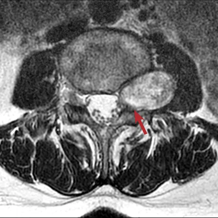
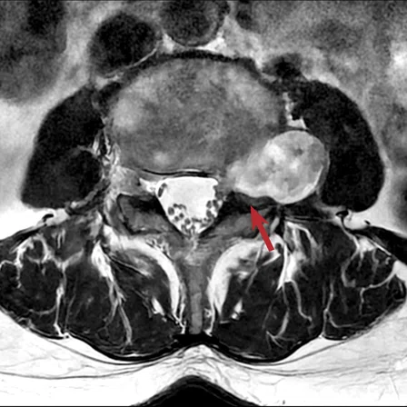
Comparison of the lumbar spine imaging in the same patient with schwannoma (A) before and (B) after the upgrade. (A) Conventional reconstruction of an axial T2 FSE, 0.6 x 0.7 x 4.0 mm, 2:43 min. (B) Axial T2 FSE with AIR™ Recon DL, 0.4 x 0.5 x 4.0 mm, 2:08 min.
B
Figure 4.
Comparison of the lumbar spine imaging in the same patient with schwannoma (A) before and (B) after the upgrade. (A) Conventional reconstruction of an axial T2 FSE, 0.6 x 0.7 x 4.0 mm, 2:43 min. (B) Axial T2 FSE with AIR™ Recon DL, 0.4 x 0.5 x 4.0 mm, 2:08 min.
A
Figure 5.
All images acquired with AIR™ Recon DL in a lumbar spine laminectomy follow-up exam. After the upgrade, it is possible to obtain oblique MPR images from coronal T2 FSE acquired at 1 mm slice thickness. (A) Sagittal T1 FSE, 0.8 x 1.0 x 4.0 mm, 1:40 min. (B) Sagittal T2 FSE, 0.7 x 0.9 x 4.0 mm, 1:28 min. (C) Coronal T2 FSE, 0.7 x 0.9 x 1.0 mm, 4:49 min. (D) Coronal T2 FSE and (E) post-processed oblique MPR.
B
Figure 5.
All images acquired with AIR™ Recon DL in a lumbar spine laminectomy follow-up exam. After the upgrade, it is possible to obtain oblique MPR images from coronal T2 FSE acquired at 1 mm slice thickness. (A) Sagittal T1 FSE, 0.8 x 1.0 x 4.0 mm, 1:40 min. (B) Sagittal T2 FSE, 0.7 x 0.9 x 4.0 mm, 1:28 min. (C) Coronal T2 FSE, 0.7 x 0.9 x 1.0 mm, 4:49 min. (D) Coronal T2 FSE and (E) post-processed oblique MPR.
C
Figure 5.
All images acquired with AIR™ Recon DL in a lumbar spine laminectomy follow-up exam. After the upgrade, it is possible to obtain oblique MPR images from coronal T2 FSE acquired at 1 mm slice thickness. (A) Sagittal T1 FSE, 0.8 x 1.0 x 4.0 mm, 1:40 min. (B) Sagittal T2 FSE, 0.7 x 0.9 x 4.0 mm, 1:28 min. (C) Coronal T2 FSE, 0.7 x 0.9 x 1.0 mm, 4:49 min. (D) Coronal T2 FSE and (E) post-processed oblique MPR.
D
Figure 5.
All images acquired with AIR™ Recon DL in a lumbar spine laminectomy follow-up exam. After the upgrade, it is possible to obtain oblique MPR images from coronal T2 FSE acquired at 1 mm slice thickness. (A) Sagittal T1 FSE, 0.8 x 1.0 x 4.0 mm, 1:40 min. (B) Sagittal T2 FSE, 0.7 x 0.9 x 4.0 mm, 1:28 min. (C) Coronal T2 FSE, 0.7 x 0.9 x 1.0 mm, 4:49 min. (D) Coronal T2 FSE and (E) post-processed oblique MPR.
E
Figure 5.
All images acquired with AIR™ Recon DL in a lumbar spine laminectomy follow-up exam. After the upgrade, it is possible to obtain oblique MPR images from coronal T2 FSE acquired at 1 mm slice thickness. (A) Sagittal T1 FSE, 0.8 x 1.0 x 4.0 mm, 1:40 min. (B) Sagittal T2 FSE, 0.7 x 0.9 x 4.0 mm, 1:28 min. (C) Coronal T2 FSE, 0.7 x 0.9 x 1.0 mm, 4:49 min. (D) Coronal T2 FSE and (E) post-processed oblique MPR.
A-1
Figure 6.
Comparison of neck imaging in the same patient with Warthin tumor between the conventional protocol and new protocol with AIR™ Recon DL. (A) Axial T2 FSE, 0.6 x 0.8 x 4.0 mm, 2:38 min. (B) Axial T2 FSE with AIR™ Recon DL, 0.5 x 0.6 x 3.0 mm, 1:17 min. (C) Coronal STIR with AIR™ Recon DL, 0.6 x 0.8 x 3.0 mm, 2:10 min.
A-2
Figure 6.
Comparison of neck imaging in the same patient with Warthin tumor between the conventional protocol and new protocol with AIR™ Recon DL. (A) Axial T2 FSE, 0.6 x 0.8 x 4.0 mm, 2:38 min. (B) Axial T2 FSE with AIR™ Recon DL, 0.5 x 0.6 x 3.0 mm, 1:17 min. (C) Coronal STIR with AIR™ Recon DL, 0.6 x 0.8 x 3.0 mm, 2:10 min.
B-1
Figure 6.
Comparison of neck imaging in the same patient with Warthin tumor between the conventional protocol and new protocol with AIR™ Recon DL. (A) Axial T2 FSE, 0.6 x 0.8 x 4.0 mm, 2:38 min. (B) Axial T2 FSE with AIR™ Recon DL, 0.5 x 0.6 x 3.0 mm, 1:17 min. (C) Coronal STIR with AIR™ Recon DL, 0.6 x 0.8 x 3.0 mm, 2:10 min.
B-2
Figure 6.
Comparison of neck imaging in the same patient with Warthin tumor between the conventional protocol and new protocol with AIR™ Recon DL. (A) Axial T2 FSE, 0.6 x 0.8 x 4.0 mm, 2:38 min. (B) Axial T2 FSE with AIR™ Recon DL, 0.5 x 0.6 x 3.0 mm, 1:17 min. (C) Coronal STIR with AIR™ Recon DL, 0.6 x 0.8 x 3.0 mm, 2:10 min.
C
Figure 6.
Comparison of neck imaging in the same patient with Warthin tumor between the conventional protocol and new protocol with AIR™ Recon DL. (A) Axial T2 FSE, 0.6 x 0.8 x 4.0 mm, 2:38 min. (B) Axial T2 FSE with AIR™ Recon DL, 0.5 x 0.6 x 3.0 mm, 1:17 min. (C) Coronal STIR with AIR™ Recon DL, 0.6 x 0.8 x 3.0 mm, 2:10 min.


result
PREVIOUS
${prev-page}
NEXT
${next-page}
Subscribe Now
Manage Subscription
FOLLOW US
Contact Us • Cookie Preferences • Privacy Policy • California Privacy PolicyDo Not Sell or Share My Personal Information • Terms & Conditions • Security
© 2024 GE HealthCare. GE is a trademark of General Electric Company. Used under trademark license.

Kumiko Ando, MD, PhD, FJCR
Kobe City Medical Center General Hospital
Kobe, Japan

Ryosuke Nasada, RT
Kobe City Medical Center General Hospital
Kobe, Japan
IN PRACTICE
An upgrade that enables MR imaging capabilities and quality beyond 1.5T
An upgrade that enables MR imaging capabilities and quality beyond 1.5T

Kumiko Ando, MD, PhD, FJCR
Kobe City Medical Center General Hospital
Kobe, Japan

Ryosuke Nasada, RT
Kobe City Medical Center General Hospital
Kobe, Japan
After completing an upgrade to AIR™ Recon DL, the radiology staff at Kobe City Medical Center General Hospital noticed a significant improvement in image quality and the ability to obtain thinner slices without a corresponding increase in scan times. The radiologists have a higher confidence in their interpretation and technologists are able to stay on schedule, even when additional sequences or emergency cases are requested. Improving image quality and shortening scan times has also increased the staff’s job satisfaction.
After completing an upgrade to AIR™ Recon DL, the radiology staff at Kobe City Medical Center General Hospital noticed a significant improvement in image quality and the ability to obtain thinner slices without a corresponding increase in scan times. The radiologists have a higher confidence in their interpretation and technologists are able to stay on schedule, even when additional sequences or emergency cases are requested. Improving image quality and shortening scan times has also increased the staff’s job satisfaction.
As the only 24-hour hospital in Kobe, Kobe City Medical Center General Hospital is an advanced, regional institution with a busy emergency department. The hospital has been ranked first in Japan’s national emergency center evaluation by the Ministry of Health, Labor and Welfare for nine consecutive years. During the recent pandemic, Kobe City Medical Center was one of the first hospitals to set up a temporary ward to treat many of the seriously ill COVID-19 patients in Kobe.
While emergency patients have a wide range of conditions and injuries, the hospital often receives many stroke and spinal cord injury cases. Equipped with four MR systems, the hospital performs 80 examinations each day, averaging 20,000 each year. Most exams are of the head (56%), spine and MSK (13.5%) and abdomen (15% upper, 9% lower/pelvis), with neck and chest accounting for the remaining body parts.
In 2021, Kobe City Medical Center upgraded its SIGNA™ Explorer 1.5T MR system to SIGNA™Works AIR™ IQ Edition (MR 29.1), featuring AIR™ Recon DL. The result has been an outstanding improvement in image quality, with higher spatial resolution and thinner slices. Specifically, slice thickness has been reduced by 20-30% and spatial resolution has increased by approximately 25%.
According to Kumiko Ando, MD, PhD, FJCR, radiologist, and Ryosuke Nasada, RT, technologist, AIR™ Recon DL is used on all compatible sequences at the highest level for the best possible SNR improvement, except for the head T2 FLAIR sequence, which is set to medium. They evaluated images from the different sequences to arrive at the high level, finding that it was best to utilize the exceptional increase in SNR. In fact, imaging parameters for all of these exams on the SIGNA™ Explorer are set to high spatial resolution, similar to the hospital’s 3.0T scanners. For example, the slice thickness was changed from 5 mm to 4 mm in head imaging, and a 2 mm slice thickness provides adequate SNR in neck imaging (Figure 1).
Clinical benefits
“The benefits of AIR™ Recon DL are enormous,” says Dr. Ando. “Among others, the image quality of head and neck, spine and orthopedics has been overwhelmingly improved, making diagnosis easier.”
In particular, Dr. Ando has found the spine image quality of SIGNA™ Explorer is outstanding, even though the acquisition time is now shorter.
In many patient cases, Dr. Ando explains that the radiologist will follow the nerve roots in the axial plane of the lumbar spine and observe which part is pressed by the intervertebral disc (Figure 4). “Now, at 1.5T we can observe which nerve root is pressed by the intervertebral disc, or by the yellow ligament, in very high-definition images.”

A

B

C

D
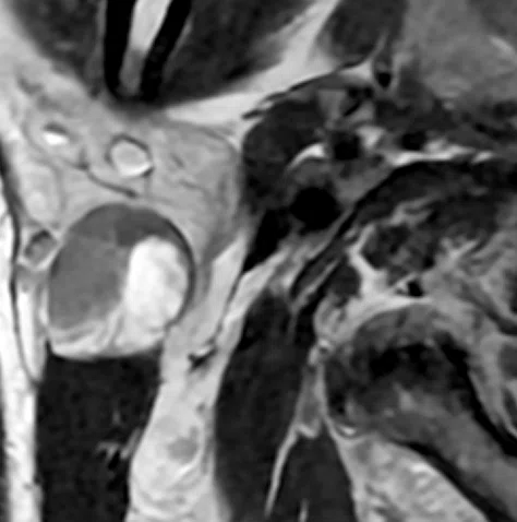
Figure 1.
STA-MCA bypass follow-up brain exam. After the upgrade, the slice thickness was changed from 1.2 mm to 0.9 mm for TOF MRA and from 5 mm to 4 mm for 2D axial acquisitions. (A) 3D TOF MRA with HyperSense, 0.7 x 0.9 x 0.9 mm, 5:34 min. (B) Axial DWI b1000 with AIR™ Recon DL, 1.4 x 1.4 x 4.0 mm, 1:28 min. (C) Axial FLAIR with AIR™ Recon DL, 0.6 x 0.8 x 4.0 mm, 3:21 min. (D) Axial T2* with AIR™ Recon DL, 0.6 x 0.6 x 4.0 mm, 1:58 min.
“It is easy to use with many sequences that can be adapted to it,” says Nasada. “The reconstruction time is not much different from that of conventional reconstruction.”
Dr. Ando notes that in Japan, there are many older MR systems in both large and small hospitals, as well as clinics. The ability to obtain higher image quality with less investment through an upgrade, rather than incurring the higher cost of replacing equipment, is beneficial to both patients and the overall healthcare system in Japan.
“We believe that AIR™ Recon DL will have a tremendous impact on the bottom line, especially for 1.5T systems,” Dr. Ando adds.
The corresponding impact of high SNR is the ability to shorten acquisition times. Now, it is easier for the technologist to accommodate additional requested sequences without falling behind schedule. For Nasada and his colleagues, AIR™ Recon DL has reduced suboptimal image quality, especially when the additional sequences are acquired within a limited time/short duration or they have a difficult-to-image patient. This reassures the technologist and reduces their stress.
“We have experienced several cases of spine imaging with the integrated body coil and without a surface coil in patients with round backs who have difficulty using the spine coil or who are unable to lie supine,” says Nasada (Figure 2).

A

B
Figure 2.
All images acquired with AIR™ Recon DL in the same patient with lumbar hernia using a (A) HNS CTL Coil and (B) integrated body coil. (A) Sagittal T2 FSE with AIR™ Recon DL and HNS CTL Coil, 0.7 x 0.9 x 3.0 mm, 1:23 min. (B) Sagittal T2 FSE with AIR™ Recon DL and integrated body coil (no surface coil used), 0.7 x 1.0 x 4.0 mm, 2:56 min.
Before the upgrade, small structures were often blurred and difficult for Dr. Ando and her colleagues to see. Now, with AIR™ Recon DL, these small structures are sharp and easier to visualize with high SNR, increasing their clinical confidence (Figure 3).

A-1

A-2

B-1

B-2
Figure 3.
Comparison of wrist joint imaging in the same patient with Kienböck disease with (A) conventional protocol and (B) new protocol with AIR™ Recon DL. (A) Coronal STIR, 0.5 x 0.5 x 2.0 mm, 3:30 min. (B) Coronal STIR with AIR™ Recon DL, 0.3 x 0.4 x 2.0 mm, 1:52 min.
Previously, it was essential to use a dedicated coil for each small structure being scanned to obtain high-quality images. Now, the technologist first uses AIR™ Recon DL and, if necessary, a dedicated coil for that small structure is then introduced. This approach further saves time.
“I think that way of thinking will change. With the high SNR and image sharpness provided by AIR™ Recon DL, even a dedicated coil may no longer be necessary,” Nasada adds.
A
B
Figure 4.
Comparison of the lumbar spine imaging in the same patient with schwannoma (A) before and (B) after the upgrade. (A) Conventional reconstruction of an axial T2 FSE, 0.6 x 0.7 x 4.0 mm, 2:43 min. (B) Axial T2 FSE with AIR™ Recon DL, 0.4 x 0.5 x 4.0 mm, 2:08 min.
“The ability to acquire 1 mm slice thickness in lumbar spine coronal images at 1.5T is amazing,” says Nasada (Figure 5).

A

B

C
D
E
Figure 5.
All images acquired with AIR™ Recon DL in a lumbar spine laminectomy follow-up exam. After the upgrade, it is possible to obtain oblique MPR images from coronal T2 FSE acquired at 1 mm slice thickness. (A) Sagittal T1 FSE, 0.8 x 1.0 x 4.0 mm, 1:40 min. (B) Sagittal T2 FSE, 0.7 x 0.9 x 4.0 mm, 1:28 min. (C) Coronal T2 FSE, 0.7 x 0.9 x 1.0 mm, 4:49 min. (D) Coronal T2 FSE and (E) post-processed oblique MPR.
The image quality of neuro MR exams has also been improved. According to Nasada, the ability to use AIR™ Recon DL without contrast limitations is very good.
Additionally, Dr. Ando is very pleased with the quality of T2, T2* and FLAIR contrast. She has also found that DWI has better spatial resolution than before, and the boundary surface between cortex and white matter can be seen clearly. Due to the SNR boost from AIR™ Recon DL, the head slice thickness was changed from 5 mm to 4 mm for DWI and T2*.
“The 1 mm thinner slice makes such a difference in the appearance,” says Dr. Ando. “For example, with the higher quality DWI, I am now able to detect cerebral microinfarcts more easily.”
In addition to the benefits attained with AIR™ Recon DL, SIGNA™Works AIR™ IQ Edition (MR 29.1) includes the next generation of HyperSense, which has improved the image quality of time-of-flight (TOF) MR angiography (MRA) of the head.
“The image quality of neuro MRA has improved dramatically by changing the imaging parameters to thinner slices and a higher phase matrix, and when used in combination with HyperSense, it is approaching 3.0T,” says Dr. Ando. The peripheral vessel visualization has also been enhanced.
“I feel that now 1.5T is more reliable for MRA compared to prior versions and is great for depicting aneurysms and post STA-MCA (superficial temporal artery to middle cerebral artery) bypass evaluations for moyamoya disease,” Dr. Ando explains.
The improved image quality of STIR has significantly benefited neck examinations. Nasada explains that previously the SNR of STIR exams was low. “Now, even with 2 mm slices, sufficient SNR is ensured and anatomy such as the parotid gland can be clearly observed,” he says.
Adds Dr. Ando, “The improvement in STIR coronal image quality is a major reason why I think the neck area is beautiful in the MR imaging we are performing (Figure 6). With AIR™ Recon DL now being compatible with PROPELLER, we believe these studies will be even better once we receive this upgrade because there will be fewer issues regarding movement and motion artifacts.”
In the neck, Dr. Ando can better see the structures in the muscles, follow the ducts of the parotid gland and clearly visualize the platysma muscle covering the fascia of the face.

A-1

A-2

B-1
B-2

C
Figure 6.
Comparison of neck imaging in the same patient with Warthin tumor between the conventional protocol and new protocol with AIR™ Recon DL. (A) Axial T2 FSE, 0.6 x 0.8 x 4.0 mm, 2:38 min. (B) Axial T2 FSE with AIR™ Recon DL, 0.5 x 0.6 x 3.0 mm, 1:17 min. (C) Coronal STIR with AIR™ Recon DL, 0.6 x 0.8 x 3.0 mm, 2:10 min.
Changing the paradigm
Six months after implementing SIGNA™Works for AIR™ IQ Edition, Kobe City Medical Center conducted a survey of its six radiologists regarding their impressions of the image quality improvements and scan time reduction.
All six said that reading MR exams has become easier and more informative after AIR™ Recon DL. They all felt the improved image quality reduces their reading stress and increases their job satisfaction. Further, one-third added that their reading time had also been reduced.
“We had this perception that 1.5T was less reliable than 3.0T in terms of image quality, but thanks to this software version with AIR™ Recon DL and HyperSense 2.0, that has changed,” Dr. Ando says. “Now, exams from SIGNA™ Explorer 1.5T are viewed as highly reliable.”
She explains that even with suboptimal image quality, it is possible to recognize an abnormality. Where the higher SNR and image quality truly make a difference is when stating in the report that there is no abnormality.
“Writing ‘no abnormality’ requires very good image quality, and thanks to AIR™ Recon DL and HyperSense 2.0, we are much more confident in the reliability of the study to make that diagnosis,” Dr. Ando adds.
Nasada also has greater confidence in the MR acquisition with AIR™ Recon DL. “When changing imaging parameters,
I used to question if I could maintain image quality. Now, I trust AIR™ Recon DL and can change to a higher resolution and shorten imaging parameters with confidence.”
Dr. Ando and Nasada have high expectations for the potential of AIR™ Recon DL 3D and PROPELLER and see a need for these solutions, particularly in upper abdomen and pelvic exams that are often impacted by motion.
“I think the use of AIR™ Recon DL 3D will be a great advancement because it will enable us to obtain high-quality, thin slice images and shorten the imaging time while using compressed sensing and parallel imaging,” Nasada says (Figure 6).
“With this advancement of AIR™ Recon DL 3D, I think it is possible that 2D sequences will be replaced by 3D sequences in the orthopedic field,” Dr. Ando adds.