A
Figure 3.
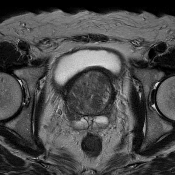
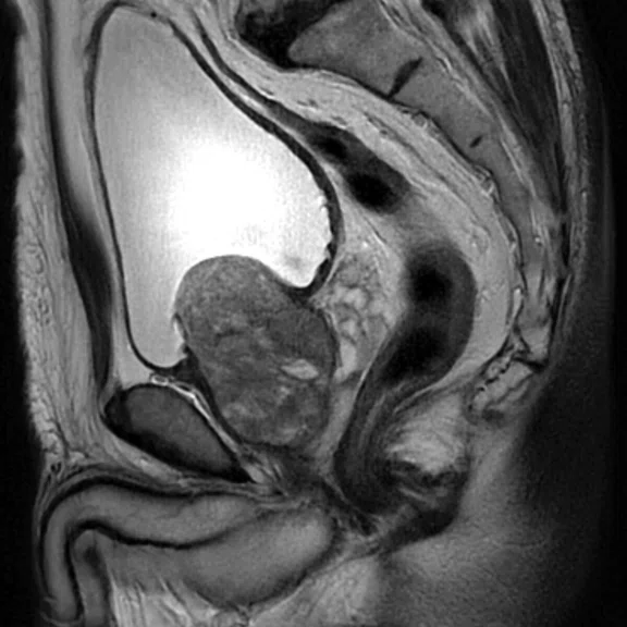
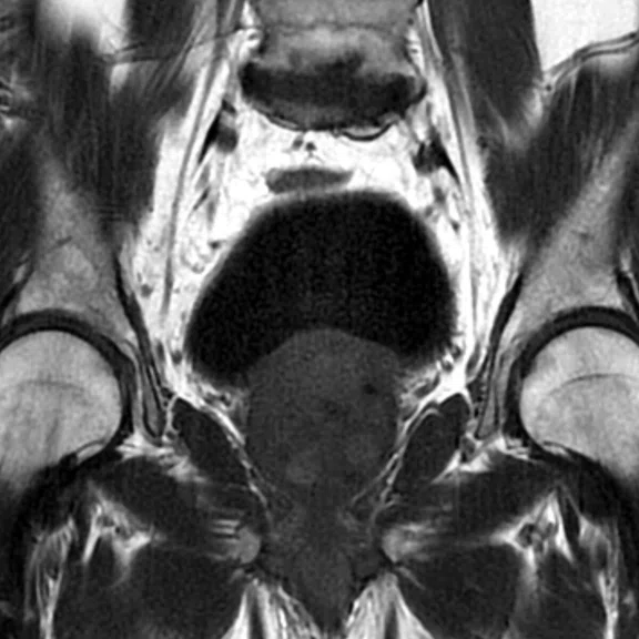
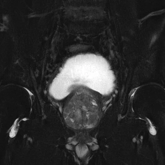
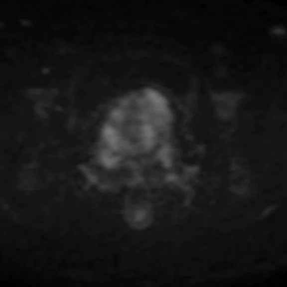
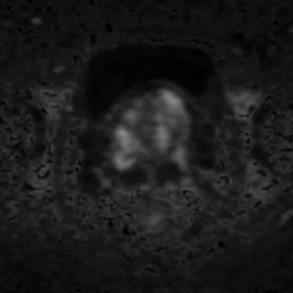
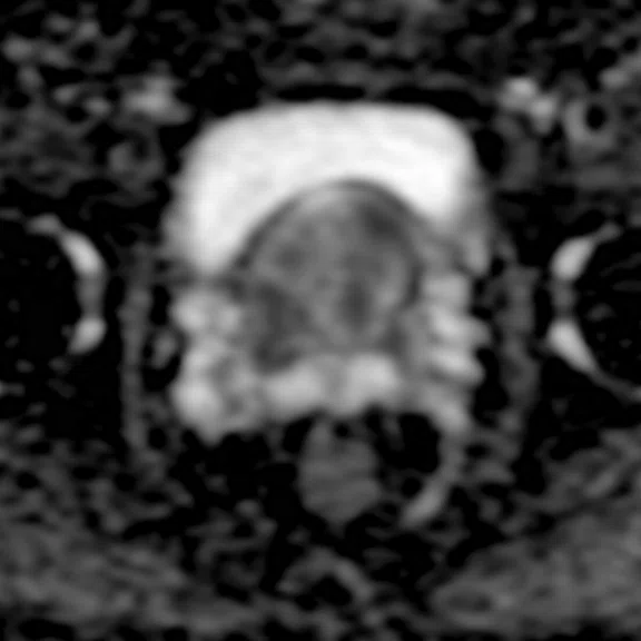
(A) Axial T2w PROPELLER; (B) sagittal T2w PROPELLER; (C) coronal T1w PROPELLER; (D) coronal T2w FatSat PROPELLER; (E) axial DWI b1400; (F) axial MAGiC DWI b2000; and (G) axial ADC map.
B
Figure 3.
(A) Axial T2w PROPELLER; (B) sagittal T2w PROPELLER; (C) coronal T1w PROPELLER; (D) coronal T2w FatSat PROPELLER; (E) axial DWI b1400; (F) axial MAGiC DWI b2000; and (G) axial ADC map.
C
Figure 3.
(A) Axial T2w PROPELLER; (B) sagittal T2w PROPELLER; (C) coronal T1w PROPELLER; (D) coronal T2w FatSat PROPELLER; (E) axial DWI b1400; (F) axial MAGiC DWI b2000; and (G) axial ADC map.
D
Figure 3.
(A) Axial T2w PROPELLER; (B) sagittal T2w PROPELLER; (C) coronal T1w PROPELLER; (D) coronal T2w FatSat PROPELLER; (E) axial DWI b1400; (F) axial MAGiC DWI b2000; and (G) axial ADC map.
E
Figure 3.
(A) Axial T2w PROPELLER; (B) sagittal T2w PROPELLER; (C) coronal T1w PROPELLER; (D) coronal T2w FatSat PROPELLER; (E) axial DWI b1400; (F) axial MAGiC DWI b2000; and (G) axial ADC map.
F
Figure 3.
(A) Axial T2w PROPELLER; (B) sagittal T2w PROPELLER; (C) coronal T1w PROPELLER; (D) coronal T2w FatSat PROPELLER; (E) axial DWI b1400; (F) axial MAGiC DWI b2000; and (G) axial ADC map.
G
Figure 3.
(A) Axial T2w PROPELLER; (B) sagittal T2w PROPELLER; (C) coronal T1w PROPELLER; (D) coronal T2w FatSat PROPELLER; (E) axial DWI b1400; (F) axial MAGiC DWI b2000; and (G) axial ADC map.
A
Figure 1.
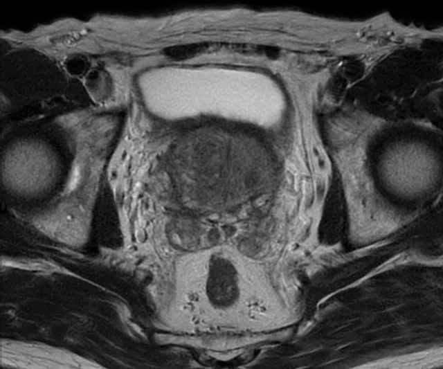
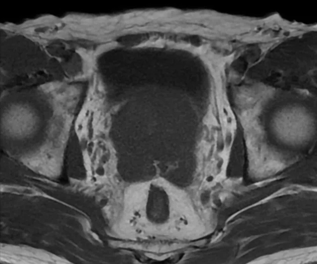
ARC with PROPELLER. (A) Axial T2w PROPELLER; (B) axial T1w PROPELLER; (C) coronal T1w PROPELLER; (D) sagittal T2w PROPELLER; (E) axial DWI b1400; (F) axial ADC map; and (G) coronal T2w FatSat PROPELLER.
B
Figure 1.
ARC with PROPELLER. (A) Axial T2w PROPELLER; (B) axial T1w PROPELLER; (C) coronal T1w PROPELLER; (D) sagittal T2w PROPELLER; (E) axial DWI b1400; (F) axial ADC map; and (G) coronal T2w FatSat PROPELLER.
C
Figure 1.
ARC with PROPELLER. (A) Axial T2w PROPELLER; (B) axial T1w PROPELLER; (C) coronal T1w PROPELLER; (D) sagittal T2w PROPELLER; (E) axial DWI b1400; (F) axial ADC map; and (G) coronal T2w FatSat PROPELLER.
D
Figure 1.
ARC with PROPELLER. (A) Axial T2w PROPELLER; (B) axial T1w PROPELLER; (C) coronal T1w PROPELLER; (D) sagittal T2w PROPELLER; (E) axial DWI b1400; (F) axial ADC map; and (G) coronal T2w FatSat PROPELLER.
E
Figure 1.
ARC with PROPELLER. (A) Axial T2w PROPELLER; (B) axial T1w PROPELLER; (C) coronal T1w PROPELLER; (D) sagittal T2w PROPELLER; (E) axial DWI b1400; (F) axial ADC map; and (G) coronal T2w FatSat PROPELLER.
F
Figure 1.
ARC with PROPELLER. (A) Axial T2w PROPELLER; (B) axial T1w PROPELLER; (C) coronal T1w PROPELLER; (D) sagittal T2w PROPELLER; (E) axial DWI b1400; (F) axial ADC map; and (G) coronal T2w FatSat PROPELLER.
G
Figure 1.
ARC with PROPELLER. (A) Axial T2w PROPELLER; (B) axial T1w PROPELLER; (C) coronal T1w PROPELLER; (D) sagittal T2w PROPELLER; (E) axial DWI b1400; (F) axial ADC map; and (G) coronal T2w FatSat PROPELLER.
1 The American College of Radiology. Prostate Imaging Reporting & Data System (PI-RADS). Available at: https://www.acr.org/Clinical-Resources/Reporting-and-Data-
Systems/PI-RADS. Accessed on Oct. 12, 2019.
A
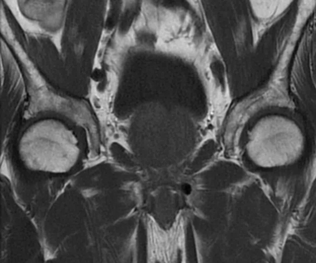
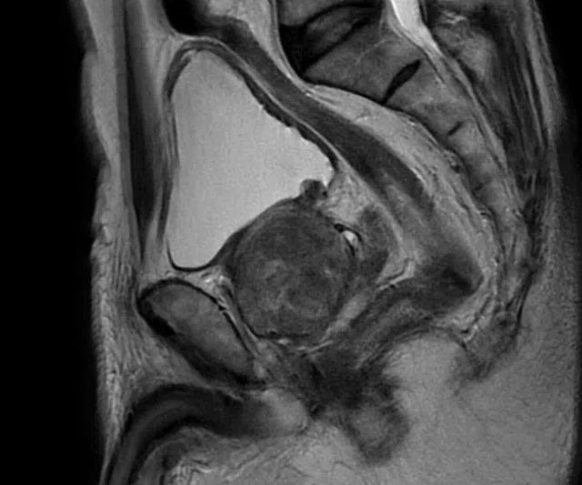
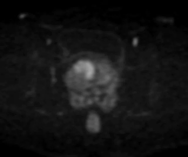
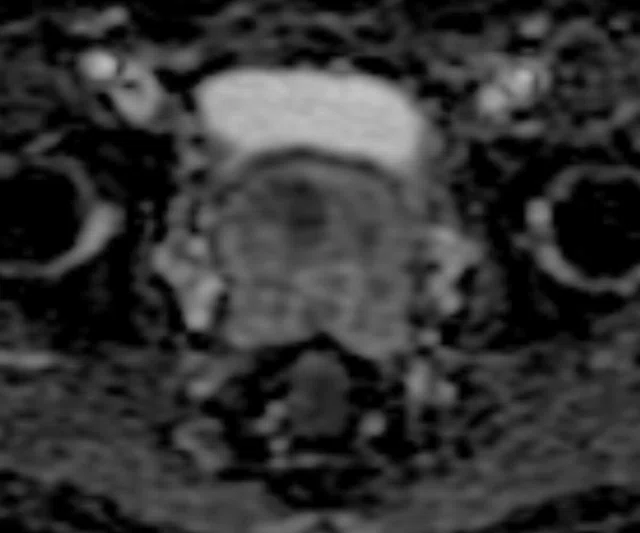
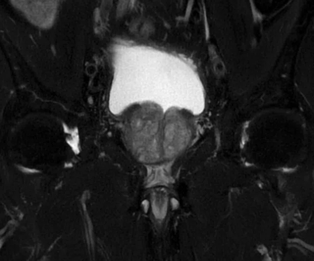
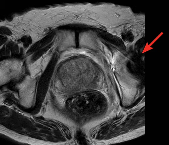
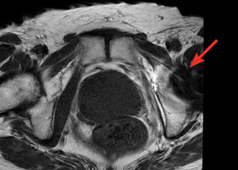
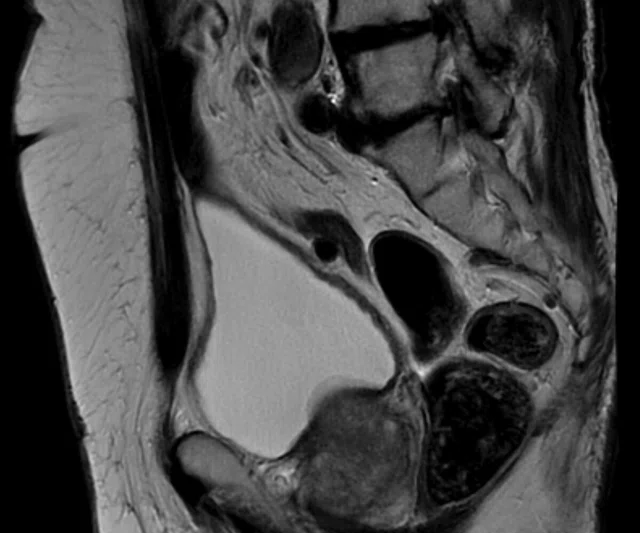
Figure 2.
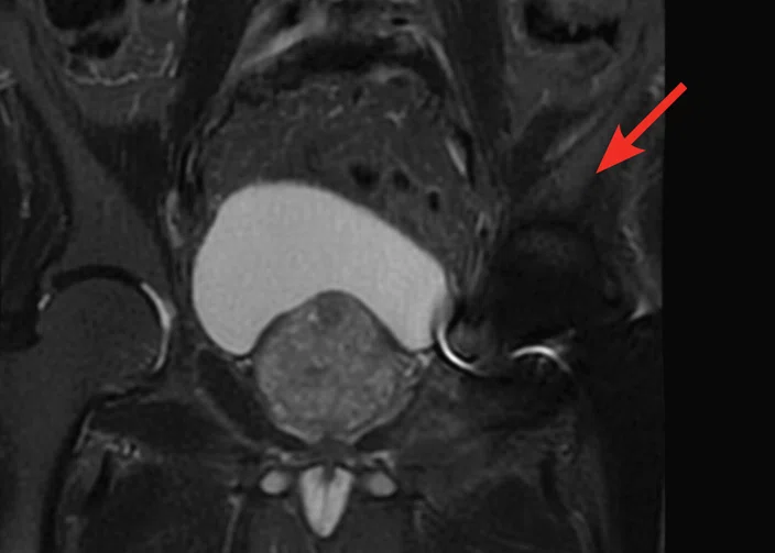
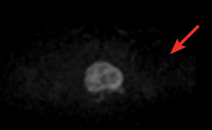
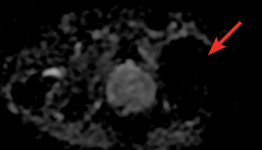
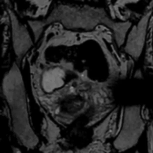
ARC with PROPELLER in a patient with an artificial joint. (A) Axial T2w PROPELLER; (B) axial T1w PROPELLER; (C) sagittal T2w PROPELLER; (D) coronal STIR PROPELLER; (E) axial DWI b1400; (F) axial ADC map; and (G) coronal T2w Cube, 1 mm slices.
B
Figure 2.
ARC with PROPELLER in a patient with an artificial joint. (A) Axial T2w PROPELLER; (B) axial T1w PROPELLER; (C) sagittal T2w PROPELLER; (D) coronal STIR PROPELLER; (E) axial DWI b1400; (F) axial ADC map; and (G) coronal T2w Cube, 1 mm slices.
C
Figure 2.
ARC with PROPELLER in a patient with an artificial joint. (A) Axial T2w PROPELLER; (B) axial T1w PROPELLER; (C) sagittal T2w PROPELLER; (D) coronal STIR PROPELLER; (E) axial DWI b1400; (F) axial ADC map; and (G) coronal T2w Cube, 1 mm slices.
D
Figure 2.
ARC with PROPELLER in a patient with an artificial joint. (A) Axial T2w PROPELLER; (B) axial T1w PROPELLER; (C) sagittal T2w PROPELLER; (D) coronal STIR PROPELLER; (E) axial DWI b1400; (F) axial ADC map; and (G) coronal T2w Cube, 1 mm slices.
E
Figure 2.
ARC with PROPELLER in a patient with an artificial joint. (A) Axial T2w PROPELLER; (B) axial T1w PROPELLER; (C) sagittal T2w PROPELLER; (D) coronal STIR PROPELLER; (E) axial DWI b1400; (F) axial ADC map; and (G) coronal T2w Cube, 1 mm slices.
F
Figure 2.
ARC with PROPELLER in a patient with an artificial joint. (A) Axial T2w PROPELLER; (B) axial T1w PROPELLER; (C) sagittal T2w PROPELLER; (D) coronal STIR PROPELLER; (E) axial DWI b1400; (F) axial ADC map; and (G) coronal T2w Cube, 1 mm slices.
G
Figure 2.
ARC with PROPELLER in a patient with an artificial joint. (A) Axial T2w PROPELLER; (B) axial T1w PROPELLER; (C) sagittal T2w PROPELLER; (D) coronal STIR PROPELLER; (E) axial DWI b1400; (F) axial ADC map; and (G) coronal T2w Cube, 1 mm slices.
A
Figure 4.
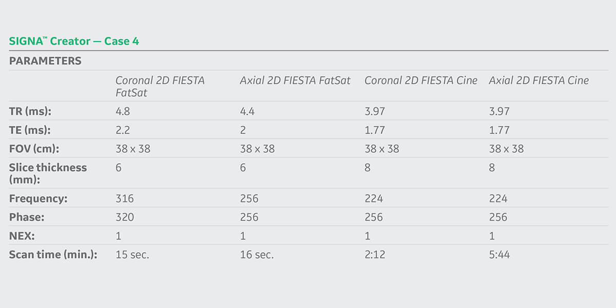
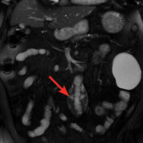
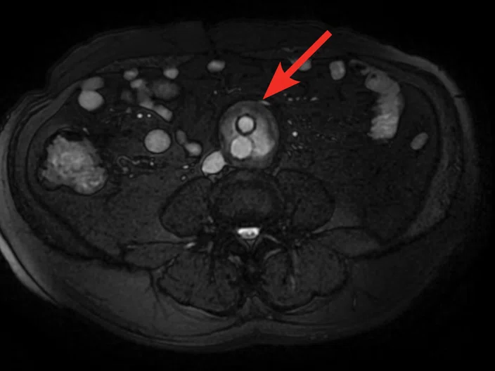
Non-contrast aortic imaging. (A) Coronal 2D FIESTA FatSat, scan time 15 sec.; (B) axial 2D FIESTA FatSat, scan time 16 sec.; (C) axial 2D FIESTA Cine; (D, E) axial CT demonstrating metal artifact (arrows) from an endovasuclar graft.; (F) coronal CT; (G) sagittal CT.
B
Figure 4.
Non-contrast aortic imaging. (A) Coronal 2D FIESTA FatSat, scan time 15 sec.; (B) axial 2D FIESTA FatSat, scan time 16 sec.; (C) axial 2D FIESTA Cine; (D, E) axial CT demonstrating metal artifact (arrows) from an endovasuclar graft.; (F) coronal CT; (G) sagittal CT.
F
Figure 4.
Non-contrast aortic imaging. (A) Coronal 2D FIESTA FatSat, scan time 15 sec.; (B) axial 2D FIESTA FatSat, scan time 16 sec.; (C) axial 2D FIESTA Cine; (D, E) axial CT demonstrating metal artifact (arrows) from an endovasuclar graft.; (F) coronal CT; (G) sagittal CT.
G
Figure 4.
Non-contrast aortic imaging. (A) Coronal 2D FIESTA FatSat, scan time 15 sec.; (B) axial 2D FIESTA FatSat, scan time 16 sec.; (C) axial 2D FIESTA Cine; (D, E) axial CT demonstrating metal artifact (arrows) from an endovasuclar graft.; (F) coronal CT; (G) sagittal CT.
C
Figure 4.
Non-contrast aortic imaging. (A) Coronal 2D FIESTA FatSat, scan time 15 sec.; (B) axial 2D FIESTA FatSat, scan time 16 sec.; (C) axial 2D FIESTA Cine; (D, E) axial CT demonstrating metal artifact (arrows) from an endovasuclar graft.; (F) coronal CT; (G) sagittal CT.
D
Figure 4.
Non-contrast aortic imaging. (A) Coronal 2D FIESTA FatSat, scan time 15 sec.; (B) axial 2D FIESTA FatSat, scan time 16 sec.; (C) axial 2D FIESTA Cine; (D, E) axial CT demonstrating metal artifact (arrows) from an endovasuclar graft.; (F) coronal CT; (G) sagittal CT.
E
Figure 4.
Non-contrast aortic imaging. (A) Coronal 2D FIESTA FatSat, scan time 15 sec.; (B) axial 2D FIESTA FatSat, scan time 16 sec.; (C) axial 2D FIESTA Cine; (D, E) axial CT demonstrating metal artifact (arrows) from an endovasuclar graft.; (F) coronal CT; (G) sagittal CT.
result


PREVIOUS
${prev-page}
NEXT
${next-page}
Subscribe Now
Manage Subscription
FOLLOW US
Contact Us • Cookie Preferences • Privacy Policy • California Privacy PolicyDo Not Sell or Share My Personal Information • Terms & Conditions • Security
© 2024 GE HealthCare. GE is a trademark of General Electric Company. Used under trademark license.
CASE STUDIES
Non-contrast prostate and vascular imaging
Non-contrast prostate and vascular imaging
By Isogai Takeshi, RT(R), and Minayoshi Shinsuke, RT(R), The Second Kawasaki Saiwai Clinic, Kawasaki, Japan
Concerns regarding the use of gadolinium-based contrast agents in MR imaging, particularly in patients with renal or kidney disease, have led to an increase in the use of non-contrast MR sequences in Japan. There is also growing awareness that many procedures involving needles such as biopsy and sedation can have potentially dangerous side effects to patients, add additional costs to procedures and extend patient recovery times. At The Second Kawasaki Saiwai Clinic, we have embraced the use of GE Healthcare’s Needle-Free Suite of sequences for many common MR imaging exams. We believe that avoiding the use of contrast can improve patient comfort, simplify workflow and reduce cost.
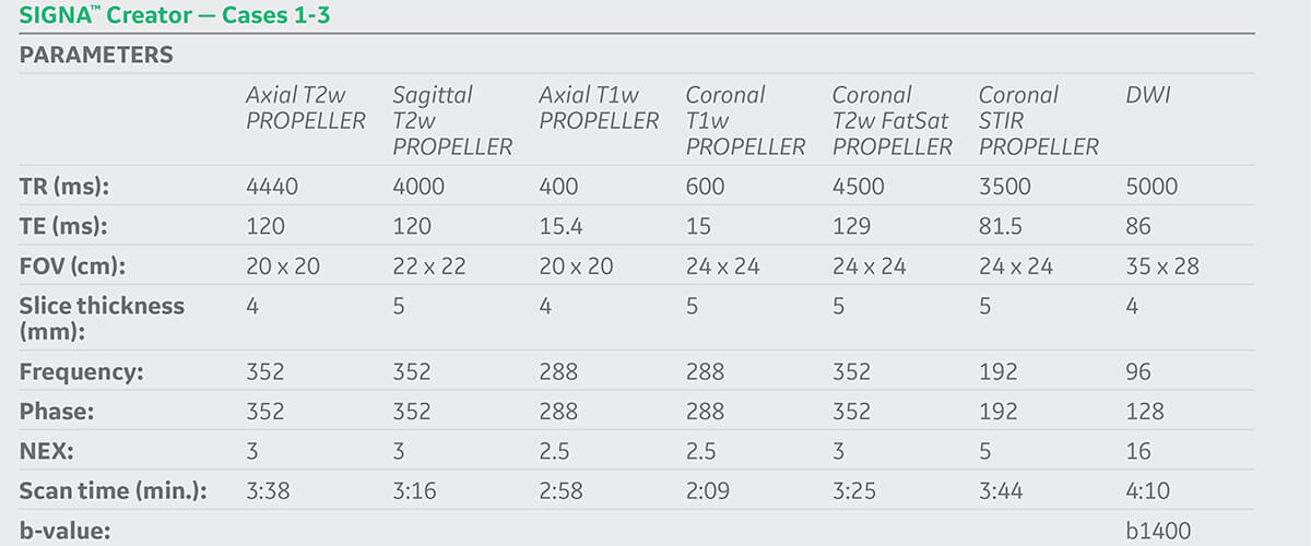
Although contrast-enhanced MR has been the current standard for non-invasive detection of prostate tumors, several studies suggest that non-contrast biparametric MR with T2-weighted and diffusion-weighted imaging (DWI) may be sufficient for diagnosis and also satisfy the requirements of PI-RADS® v2.1.1 For non-contrast prostate exams at The Second Kawasaki Saiwai Clinic (Kanagawa, Japan), the use of PROPELLER and DWI are important for the detection of cancerous tumors (see Cases 1-3).
PROPELLER reduces effects of patient voluntary and physiologic motion without sedation, and reduces susceptibility artifacts. Since The Second Kawasaki Saiwai Clinic uses PROPELLER MB to minimize motion artifacts they do not need to use glucagon or a paralytic drug to suppress bowel motion. DWI provides high SNR diffusion images with short acquisition times and multiple b-values to provide measurement of apparent diffusion coefficient (ADC) map with reduced effect of perfusion.
In addition to prostate imaging, we also find that non-contrast MR is very useful for the follow-up of stent grafts to detect endoleak (see Case 4). Historically, CT imaging is used to follow-up patients after performing a stent graft treatment. However, because stent grafts are composed of artificial blood vessels (grafts) and metal frameworks (stainless steel, nitinol), the quality of the CT exam is often affected by metal artifacts. MR imaging is typically less impacted by metal artifacts and is therefore often utilized for these cases.
Case 1
Patient history
A 79-year-old patient referred for MR exam for suspected prostate cancer.
MR findings
PI-RADS® score 4 with a lesion slightly smaller than 7 mm in the transition zone detected on DWI with ADC map.
Case 2
Patient history
A 77-year-old man with persistent, high PSA and history of benign prostatic hyperplasia. Patient previously underwent surgery on his left femoral head and has an artificial joint.
MR findings
Prostate cancer, enlargement of prostatic intraepithelial neoplasia.
Case 3
Patient history
A 71-year-old man with persistent, high PSA and history of benign prostatic hyperplasia.
MR findings
Prostate cancer with PI-RADS® score 4.
Case 4
Patient history
A 84-year-old man referred for MR exam for follow-up one month after an endovascular aneurysm repair. Metal artifacts obscured the anatomy on CT, necessitating the use of MR for suspected endoleak.
MR findings
Type III leak from stent graft in leg detected using non-contrast-enhanced blood vessel imaging.


